Some simple models of electric boilers do not have a smooth power regulation by degrees, not to mention broader functionality. But even in the presence of degree-controlled regulation, the operation of the automation is based on measuring the temperature of the coolant in the supply and return of the boiler, which is not entirely effective: high accuracy cannot be achieved, high inertness is characteristic, that is, a rather slow change in the air temperature in the house.
But the main thing is that in the absence of precise adjustments, a lot of electricity is wasted.
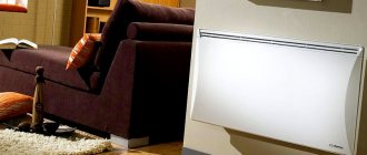
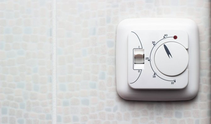
The problem can be solved by installing a special room thermostat (thermostat) for an electric boiler, the more expensive models of which measure the air temperature in the room and regulate the boiler operating mode in accordance with it, which is more correct and, most importantly, saves from 10 to 30% of electricity. Moreover, the price of the issue is only 800-1000 rubles for simple mechanical models or 3-5 thousand rubles for more functional programmable thermostats controlled from the phone.
What are thermostats for an electric boiler
What are they for and how they are used
Simple mechanical thermostat.
The temperature controller is a wired or wireless control panel that is mounted on the wall in any convenient place.
There are both simple mechanical models, the functionality of which is smooth temperature control by degrees (especially important for electric boilers with mediocre 3 or 6-step power control), and automatic programmable models with an information display, which allow you to set more than 50 parameters of the boiler operation, program them change for the next day and even a week.
Automatic thermostats allow you to adjust the boiler operation once and up to a whole or even several heating seasons.
In general, room thermostats for electric boilers perform functions such as:
- measurement, control and maintenance of a certain comfortable temperature of the working environment;
- transmission of signals to the electric boiler from any place convenient for the owner in the house;
- protection against overheating or freezing of the heating system;
- programming the operating mode for the next day or week;
- remote control from the phone if there is a Wi-Fi or GSM module in the thermostat;
- remote notification (including via a smartphone) about malfunctions and emergencies in the operation of the heating system.
Existing types
The settings made on the thermostat have priority over the settings of the electric boiler itself. The principle of operation of the device depends on the type of temperature sensor used in it:
1. Mechanical thermostats
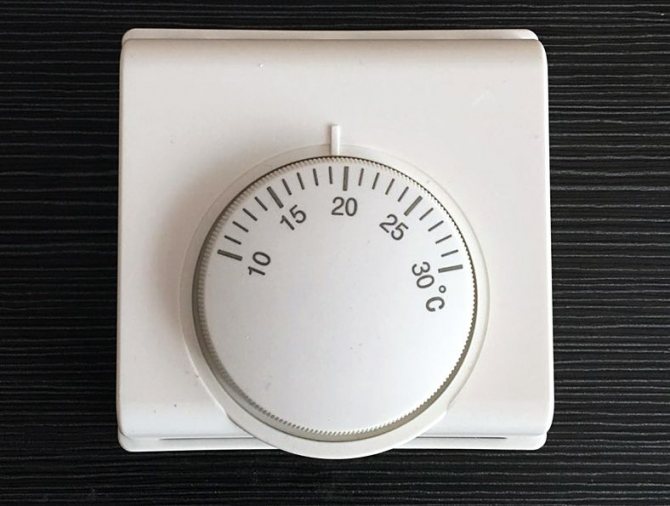
The simplest models, the principle of which is based on the operation of membrane and capillary temperature sensors. They use substances that significantly expand at the slightest increase in temperature, placed in a capsule. The expanding substance, upon reaching the maximum temperature threshold, exerts pressure on the relay membrane, as a result of which the contacts open, the thermostat signals a partial or complete decrease in the power of the electric boiler.
The main disadvantages of such thermostats are simple functionality, limited by turning a round rotary knob to set the desired temperature, and a high error - up to 3-4 ° C.
2. Electromechanical
They have a more complex design, based on which special metal plates are used as a temperature-sensitive element, producing a micro-discharge when heated to a certain temperature. The micro-discharge activates an electromagnetic relay that controls the mechanical valve. In general, electromechanical thermostats have + - the same functionality, but a much smaller error, their cost is 20-40% higher.
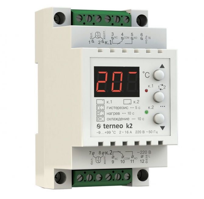
3. Electronic
The most modern and multifunctional devices equipped with electrical boards (automation), often with external sensors: both internal and external (outdoor). They are able to maintain or change the operating mode of the electric boiler without human intervention. Allow a minimum error of up to 0.5-0.7 degrees. We recommend paying attention to electronic thermostats in view of their functionality and economy.
Automation of modern models is able to maintain the most economical mode of operation of the electric boiler, constantly adjusting its operation in accordance with the temperature in the working room, which completely prevents unnecessary consumption of electricity. After all, reducing the temperature by 1 ° C is up to 5% savings.
How to choose an external temperature sensor and organize weather-dependent boiler control
Replacing the contactor in the electric boiler with a modular version
Hello to all readers of my site!
Continuing the topic of electric boilers for the home, I want to tell a story from practice.
A client turned to me with a request to help in solving one problem.
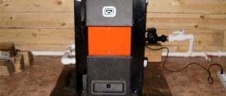
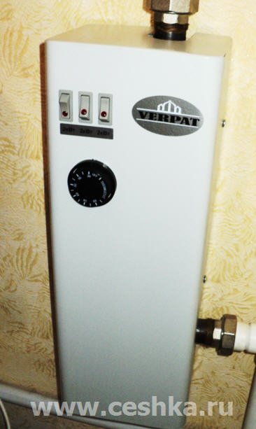
An electric boiler installed at home turned on / off very loudly during operation.
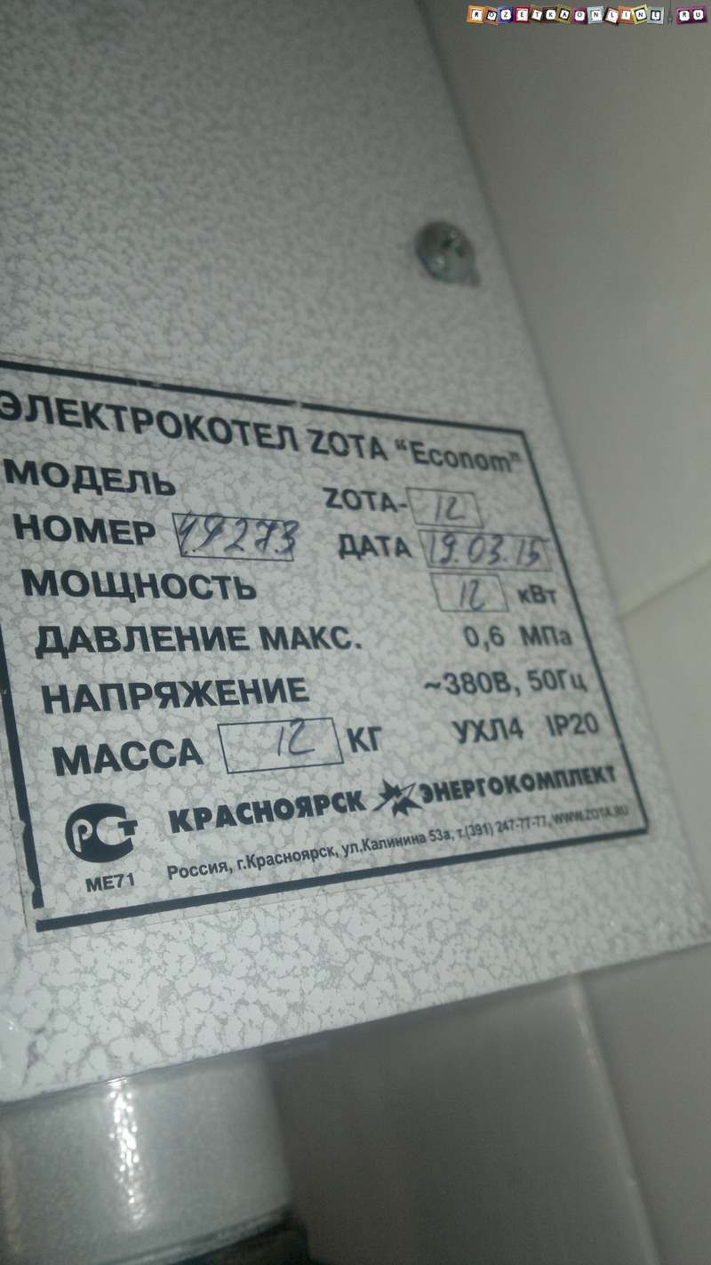
A boiler with three heating elements with a power of 6 kW, connected to one phase, that's what I found out earlier by phone.
There is also a simple automatic temperature control that acts on / off. contactor, which emits loud "slaps" when switching.
Everything would be fine, but the electric boiler is not installed in a separate room - the boiler room, but in the kitchen not far from the bedroom and it really interferes with rest ... Imagine - sleep at night and you will be woken up by periodic “BA-BAH!” )))
Having found out all this, I went to the place to see how you can help in this case, how to make the electric boiler silent.
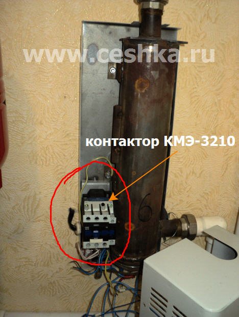
It turned out that the electric boiler had already gone through one replacement of the contactor, before that a small-sized contactor KME with a rated contact current of 20 amperes was installed (according to the owners). It broke down and was replaced with exactly the same but larger size - KME-3210.
Because of what they changed the contactor, as they explained to me, one heating element on the electric boiler stopped turning on and the contactor sparked strongly during operation. This contactor worked quite a bit and its contacts burned out, the connection of the electric circuit was broken and the current to one heating element stopped "passing", naturally this heating element stopped heating.
This surprised me a little, since the load of the three heating elements for the starter fully corresponded, 6 kW is about 28 amperes, and the contacts at the contactor were paralleled and only the phase was switched through them, and it turns out that through three contacts a current of up to 60 mapere could flow for a long time time without any consequences.
And then it turns out that from half of the permissible current of 30 amperes, the contacts are out of order ...
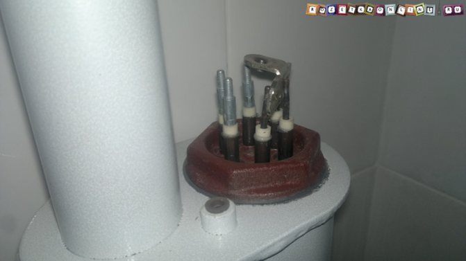
Something is wrong here. Just in case, I check the heating element with a multimeter by resistance (by the way, they are connected according to the “star” scheme) - everything is fine, the resistance is the same as it should be, because the heating element is of the same power of 2 kW.
I check the resistance of the heating element relative to the case - everything is also clean, the insulation is good.
I turn on the machine on the electric boiler and measure the voltage, so that's where “the dog rummaged!”))) And the voltage is low - only 190 volts!
This is the reason for the rapid failure of contacts.
Due to the low voltage, the moving part of the magnetic circuit in the contactor was poorly pulled up to the fixed one - as a result of this, there was a poor clamping of the power contacts between themselves, and already because of this, increased wear of the contacts, which led to their burnout and breakdown.
By the way, you can see how low voltage affects the switching on of the contactor in my articles
I figured out the reason for the failure of the contactor, I recommended the owners to contact the power supply organization about the low voltage, then we still need to solve the issue of noisy turning on the contactor.
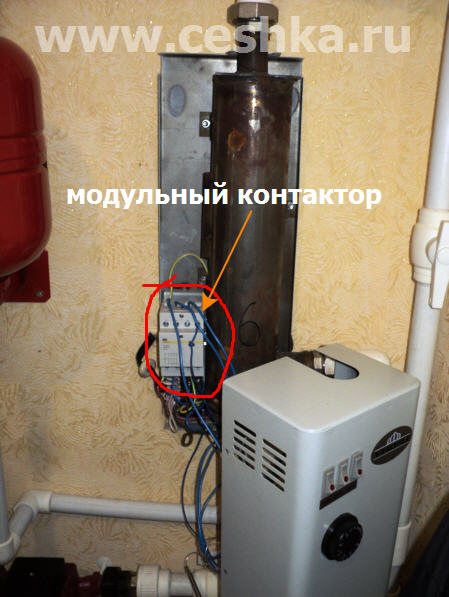
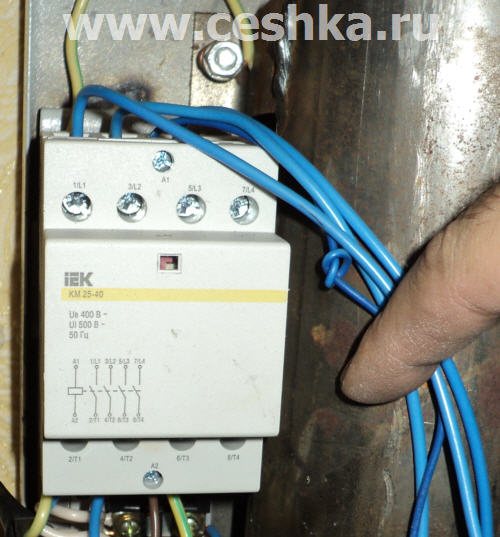
Here it is - the reason for "babakhaniya" - the KME contactor:
It is difficult to move the electric boiler to another place, winter is coming in the yard, there is no time to rework the heating system, so I suggested replacing the KME contactor with a modular contactor, since when the latter is triggered, it emits much less noise and, moreover, is smaller in size than the KME- 3210.
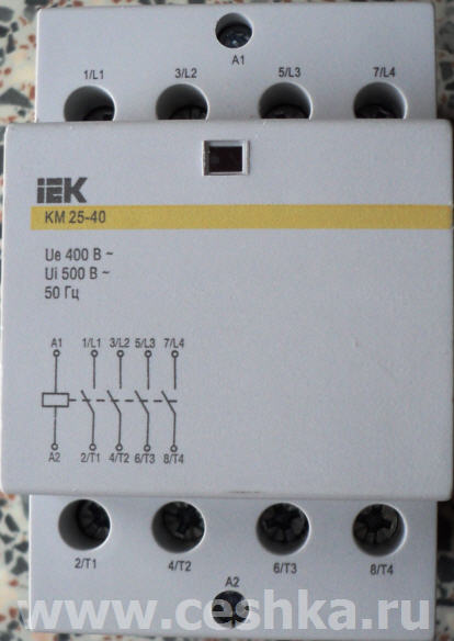
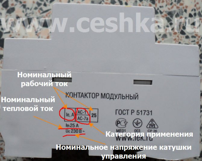
A modular contactor from IEK KM-25-40 with a rated contact current of 25 amperes was purchased. Each heating element of 2 kW is no more than 10 amperes, and the contact is designed for 25 amperes, so everything is in order in terms of load.
A small problem came out with the fastening of the modular contactor - the seat was not suitable for it, I had to install a din-rail on top, well, as they say, it's a matter of technology)))
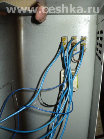
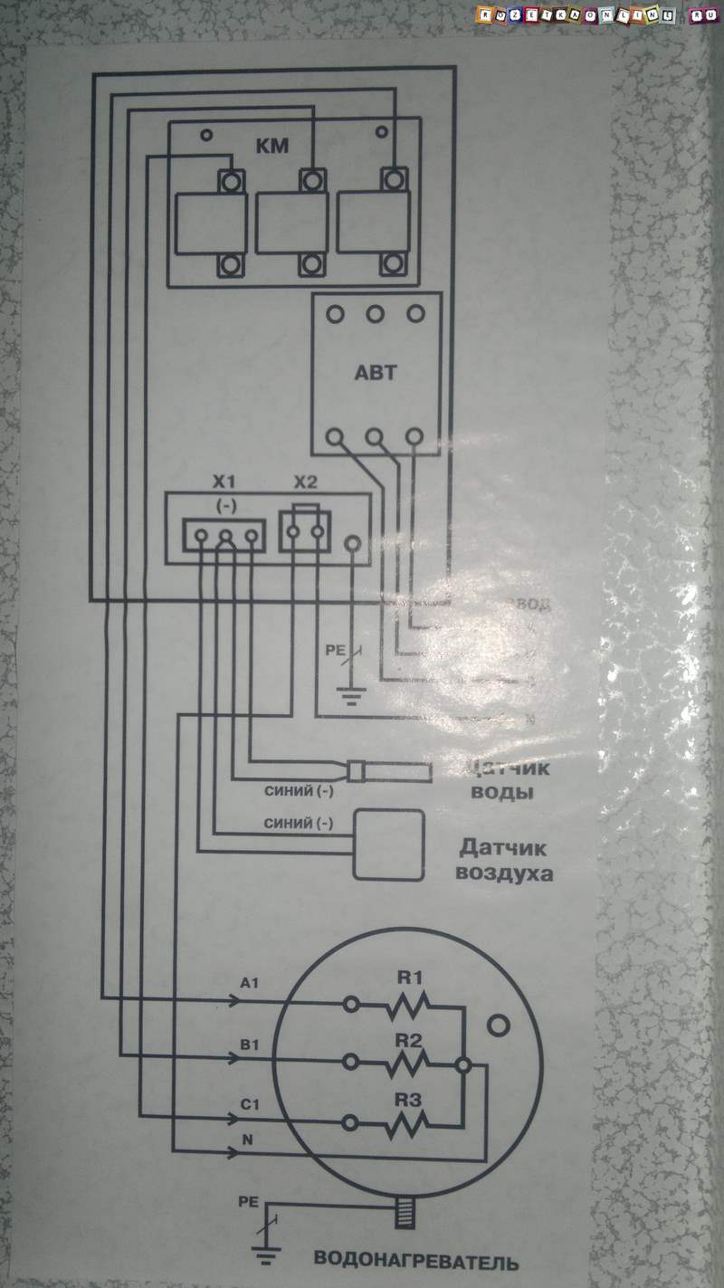
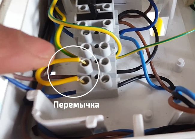
The contactor is connected in the same way as the KME, nothing has changed here, three wires go from the terminal block to the lower contacts (on the terminal block, these three wires are connected by jumpers to the phase wire), and from the upper ones they go along the wires to the switch keys installed on the removable front of the case electric boiler.
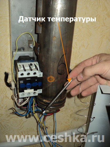
The zero wire goes directly to the heating element terminals and another zero wire, through the temperature sensor, to the contactor coil. A phase wire from the terminal block is connected to the second output of the coil.
And here is the reverse side of the removable part of the electric boiler body:
After assembling the circuit, I turned on the machine and checked the operation of the contactor - the sound when turned on became much quieter and almost inaudible! The client was very pleased)))
For those who read my site, I specially recorded a video where I showed how the KME contactor worked and how the electric boiler turns on after installing the modular contactor.
In the video, the sound turned out to be quite loud - in fact, the sound of switching on the modular contactor is not louder than the sound of flipping the switch keys - pay attention by watching the video!
And for the most attentive, when I showed the switch on from the KME, it is clear that the third light on the key does not light up well, as if from a bad contact ...
In fact, it turned out to be so - in the contactor one of the wires going to this button was inserted into the clamp together with the insulation and the contact was very bad. Apparently the electrician who connected this boiler was either inattentive or in a very hurry somewhere)))
So, watch the video:
I will be glad to your comments, if there are any technical questions, then I ask you to ask them on the forum, it is there that I answer the questions- FORUM .
Subscribe to my youtube channel ! Watch many more home electrics videos!
How to choose a room thermostat for an electric boiler
Mounting and connection method
According to the technique of fastening and connecting to the electric boiler, wired and wireless devices are distinguished.
Wired thermostats can still be installed in any room, they can have any functionality, but they require a wired connection directly to the electric boiler. Their cost is lower, and in most cases the wire for connection is included in the kit.
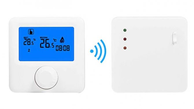
Wireless temperature controllers consist of a control panel and a radio signal receiver connected to the electric boiler by a wired method.The advantages are obvious: when the thermostat is located in a room remote from the installation site of the electric boiler, it is not necessary to lay an additional electric wire through the whole house.
According to practice, a 433 or 868 MHz radio signal intended for household appliances does not affect other electronics in the house, it is transmitted without problems through any walls at a distance of 20 or even 30 meters. The disadvantage is the need for additional power supply to the control panel, usually 2 standard AA batteries.
Functionality
Standard simple models only have an on / off switch and a rotary knob (or buttons "+" "-") to set the temperature.
For substantial savings, it is best to opt for a more expensive programmable thermostat that will pay off in the first few months of use. It can be used to lower the room temperature to 15-16 ° C when everyone has gone to work, or 18-19 ° C at night. It is enough to configure several patterns of the electric boiler operation once, the duration of which can be in the range from 8 hours to 7 days.
In addition, in addition to the built-in temperature sensor, programmable models are often equipped with additional remote ones, including those for warm floors.
Availability of Wi-Fi or GSM-module
The built-in GSM-module allows you to receive SMS messages about the operation of the heating system or about an emergency situation that you can immediately resolve. Thus, the coolant will not freeze during a long absence of the owners.
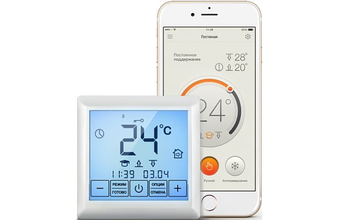
The presence of Wi-Fi allows you to control the operation of the electric boiler through an application on a smartphone. Also, via a Wi-Fi network, you can connect the thermostat to a smart home system or link several additional temperature sensors (including a warm floor). The presence of Wi-Fi and GSM does not affect the efficiency and economy of the heating system, but increases the comfort of its use.
Protection and safety
In budgetary and even in some models of electric boilers in the middle price segment, basic safety elements such as overheating protection, frost prevention mode or protection against stopping the circulation pump may be missing. Nevertheless, all these elements are present even in many simple models of thermostats in the price range of 1,000-1,500 rubles.
Such security systems should not be neglected especially when temporarily living in a house, when the owners are absent for days or weeks, but the heating system maintains a positive temperature.
Contactor function
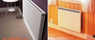
Heating with electric convectors is characterized by low inertia. To maintain a comfortable temperature, the devices have to work in intermittent mode. With high load and switching frequency, it is impossible to place switching devices in the same housing with thermostats, which are traditionally made in the form of a compact panel. Therefore, this type of heating implies the organization of two networks: load or power, as well as a control one, which controls the operation of the first network.
Compact and modular contactors allow switching fairly high loads - up to 63 A at each pole. In this case, the current strength in the supply circuit of the contactor itself is negligible, it rarely turns out to be higher than a few tenths of an ampere. Such a small load is quite within the power of the control circuits of all types of thermostatic devices. Thus, the switching on and off of heating devices is performed in steps, which contributes to an increase in the service life and maintainability of the entire heating system.
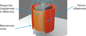
Scheme and principle of operation of a three-pole contactor: 1 - fixed power contacts; 2 - movable core with contacts; 3 - load; 4 - electromagnetic coil
It is important to understand that the contactor is able to handle a significant load not only due to more massive live parts and an increased contact area.The mechanism of these devices provides for the possibility of ultra-fast closing and opening of the contact group, plus devices for accelerated extinguishing of the electric arc are located inside the case. It is these differences that allow the contactors to operate several hundred times during the day without experiencing overheating and without the formation of carbon deposits on the contact surfaces. Therefore, the installation of a contactor is strictly recommended even if the switching capacity of the thermostat relay group (usually 10 or 16 A) significantly exceeds the consumption currents, for example, when a 500–800 W convector is connected to it.
The best known manufacturers and models: characteristics and prices
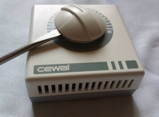
Cewal RQ-10
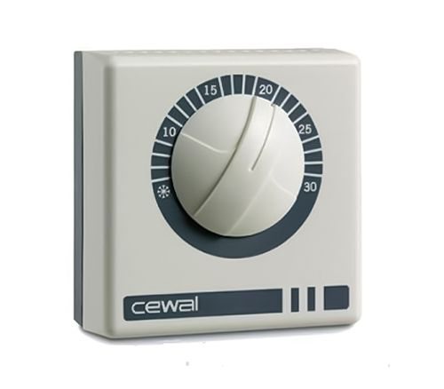
One of the simplest and most affordable mechanical thermostats from an Italian manufacturer. Despite the low cost, it is known for its build quality and reliability. The instructions for the device schematically and in detail indicate the installation and connection algorithm. The only drawback is the large hysteresis - up to 1.5-2.5 degrees, which is typical for all mechanical thermostats.
Cost: 800-1 150 rubles.
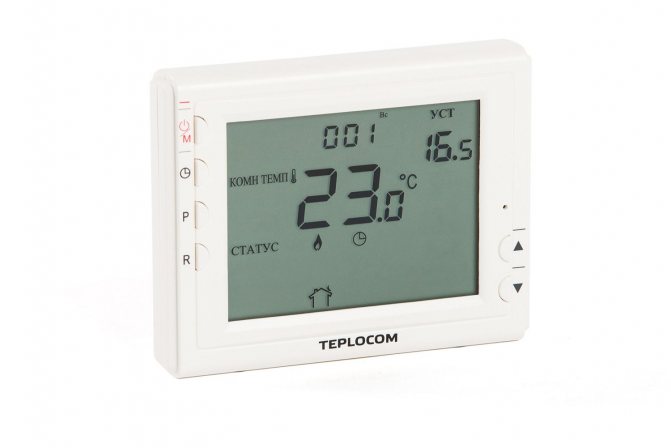
SKAT Teplocom TS-2AA / 8A
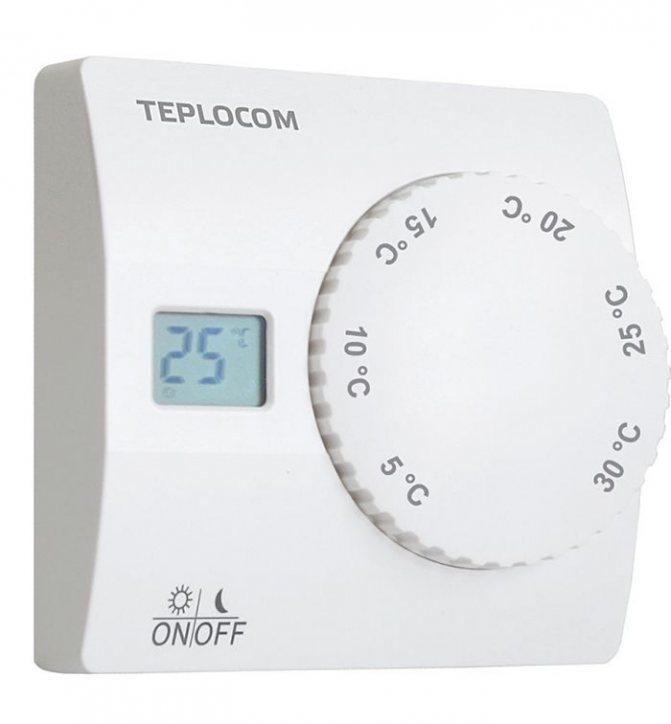
More advanced thermostat with an accuracy of up to 1 ° C. It has a micro-display for temperature indication, it is powered by 2 AA batteries (enough for 10-15 months). Differs in the presence of an economical night mode with automatic temperature decrease by 4 ° C and the presence of frost protection.
Cost: RUB 1,450-1,600
Danfoss ECtemp Next Plus
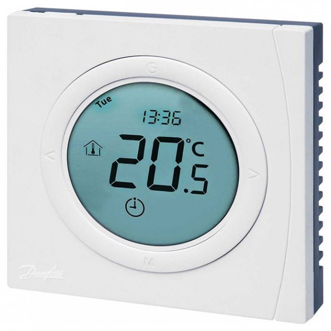
One of the best thermostats for an electric heating boiler in a price-quality-functional ratio. It is a modern electronic programmable thermostat with a stylish design and wide functionality. In addition to the built-in one, it has a remote wired temperature sensor for underfloor heating, which allows control separately from the air temperature in the room. Wide functionality, programming and availability of ready-made modes ("night", "away", etc.) allow you to maximize energy savings.
It is also distinguished by safety: the presence of protection against overheating and freezing, child blocking, monitoring the health of temperature sensors. According to the practice of installation and feedback from the owners, there were no cases of malfunction. In order to avoid malfunctioning, the assembly must fit exactly into the grooves of the plug connector.
Cost: 3 420- 3 900 rubles.
TEPLOLUX MCS-350
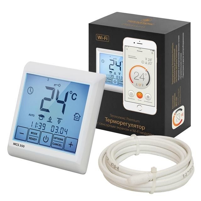
A modern multifunctional premium thermostat with a built-in Wi-Fi module and the ability to control using a special application for a smartphone. It features one of the broadest functionalities, an informative touch screen (with automatic locking) and a stylish design. The set includes both built-in and remote temperature sensors for simultaneous or separate control. Additionally, you can connect up to 32 temperature sensors.
There are template energy-saving operating modes and weekly programming, energy consumption statistics. The connection must be made via a modular contactor.
Cost: 5,900-6,200 rubles.
Control method
Unlike magnetic starters for controlling motors and other types of consumers, the contactor for convectors works on a different principle. In the case of switching electrical heaters, a self-pickup circuit is not required. Thus, the contactor does not have to have additional blocking contacts, their presence only leads to an unjustified increase in the cost of the electrical installation.
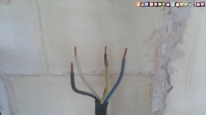
Since the power supply to the contactor coil is controlled by an additional device, the assembly scheme is extremely simple. A wire of three or more cores is laid to the installation site of the thermostat. Two of them - phase and zero - power supply of the thermostat itself. In this case, the phase is also used as a power supply for the midpoint of the relay group.The third and other additional conductors are a signal return for connecting one or more contactors.
Wiring diagram for convectors through a contactor: 1 - automatic switches; 2 - cross-module; 3 - contactor; 4 - thermostat; 5 - electric convectors
The location of the thermostat is determined taking into account two circumstances. The first is the requirement for ease of access for control, while the thermostat should not disturb the interior composition. The second aspect is the proximity to the location of the temperature sensor. Typically, the thermosensitive element is placed on the ceiling, with the cutoff temperature selected 3-4 ° C higher than that which must be observed in the habitable area of the room. The response hysteresis is selected within the range of 2-3 ° C, thus, the supply of overheated air in the upper zone provides a minimum inertia, which provides the room with residual heat during the downtime of the heating devices.
Looking ahead, we note that such a control scheme is not always the most convenient and therefore is not the only one. The very fact of using contactors allows the use of completely different control systems: remote, timing, as well as combined and even with switching to manual.
Correct connection of the thermostat to the electric boiler
When choosing an installation site, it must be borne in mind that:
- installation near windows, ventilation or entrance doors is not recommended due to constant temperature changes;
- heated air masses are concentrated near the ceiling, closer to the floor the temperature is lower, therefore it is recommended to install the thermostat at a height of 1-1.5 m;
- Household appliances in the kitchen can generate heat, which affects the accuracy of measuring the overall climate in the workroom.
- it is not recommended to install too close to a frequently closed door;
- direct connection is not recommended if the load exceeds 10 A (connection is made via a modular contactor).
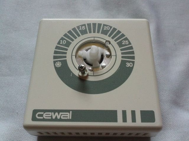
Connection instructions using the example of a mechanical Cewal RQ-10:
| Photo | Process description |
| Remove the rotator |
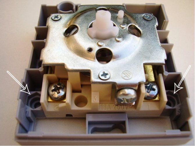
| Unscrew the screws by removing the front cover of the thermostat |
| Attach the device to the wall using the appropriate holes |
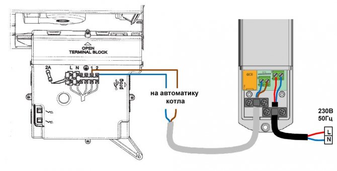
| Connect the ground. According to the diagram in the photo (click to enlarge), it is necessary to connect the thermostat contacts to the electric boiler board. |
| Individually... There can be a jumper between the “TA” contacts of the boiler board; it must be replaced with a two-core insulated cable with a conductor cross-section of 0.5-0.75 mm2. |
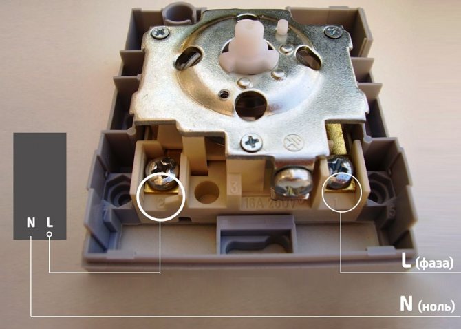
Modern thermostats are powered by AA batteries, but connection to the mains may also be required according to the diagram below:
Connection diagrams and a detailed algorithm are described in the instructions for each of the thermostats. However, each case is different and requires certain basic knowledge and skills. Therefore, the traditional advice - in case of difficulties and difficulties, contact the specialists.
Installation site and wiring
Despite the compact dimensions of modular contactors, it is not customary to place them in residential premises. The reason for this is simple: a modular flap, even of a hidden type, disturbs the appearance of the finish; moreover, during operation, contactors cannot boast of an absolutely zero noise level. However, the placement of switching devices in habitable rooms is not required, all the same, the power supply of the power lines with electric heating is carried out from the ASU, it is there that it is best to place the control assembly.
Naturally, all convectors in a building do not have to be connected via a single contactor controlled by a single thermostat.As a rule, for each living room, its own circuit is assembled, in which, depending on the number of convectors, either several single-pole contactors or one multi-pole contactor are used. Connecting several lines to one pole of the contactor is highly undesirable, otherwise repair work in one area will require disconnecting the entire group.
The practice of connecting powerful electrical appliances with separate lines fully fits into the specifics of modern electrical installation. Unlike general-purpose outlet groups, it is not customary to use junction boxes in the heating network. A separate 3x2.5 mm2 cable is laid from the control panel to each convector, to which only one heating device is connected.
Depending on the building plan, the layout of the electrical distribution network may differ. For example, if in a large building there is a possibility of placing intermediate shields in an uninhabited area, one main line, protected by separate machines, will follow from the ASU to them. In each panel, an assembly of contactors is installed, connected by a signal wire to the local control device, and then a branched power supply network of consumers is laid with separate lines.
Electrical installation
A typical assembly diagram of an electrical panel begins with an input device, which in this case is optimal for a differential machine. Its output terminals are bridged to the cross-module, from which further wiring is performed. Since contactors are not designed to protect against short-circuit currents, it is better to use double-row shields for optimal layout of electrical devices. In the top row, the required number of circuit breakers is set to protect each line. Directly under each of the machines, a corresponding contactor is installed, to which the phase conductor of the line that it controls is connected is connected. When connecting the power cables of the convectors, the protective and working neutral conductors are not combined at any point in the circuit, they are wired to different blocks of the cross-module.
Connection diagram for electric convectors: 1 - input automatic machine; 2 - counter; 3 - RCD / difavtomat; 4 - cross-module; 5 - automatic switch; 6 - thermostat; 7 - air temperature sensor; 8 - contactor; 9 - electric convector
The situation is complicated when the control devices are also mounted in a modular panel. These can be both programmable thermostats with a remote sensor, and remote control devices ("Xital") or logical controllers (CCU). In such cases, the shield should be three-row: in the upper row, an input device is installed together with control and automation devices, the lower two are diverted to accommodate circuit breakers with contactors.
Since the supply lines of the convectors are fixed-type wiring, they should be carried out with a cable with single-wire vinyl-insulated conductors. Such conductors do not require crimping to connect to the terminals; it is enough to simply strip them and roll them into a ring. If the number of controlled lines is more than two, it is highly desirable to carry out marking: at the point of cable entry into the shield, a belt tag clings, while the phase conductor is crimped with a corresponding cable mark at the end.
Control wiring, as mentioned, is represented by a cable with three or more conductors. Neutral (blue) is connected to the corresponding block of the cross-module, phase - to the output of the low-current circuit breaker. The rest of the cores, according to the marking, are connected to the terminals of the contactor coils, marked with the letter A with index 1 or 2. The second terminal is connected with a jumper to the neutral block of the cross-module.
Note: this connection is correct only if the supply voltage of the contactor coils is mains, if 24 or 36 V devices are used, the circuit is supplemented with a step-down transformer. In this case, an additional conductor must be provided in the signal cable going to the thermostat, through which the reduced voltage is supplied to the middle point of the contacts of the relay group of the thermostat.
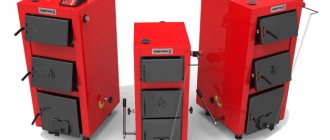
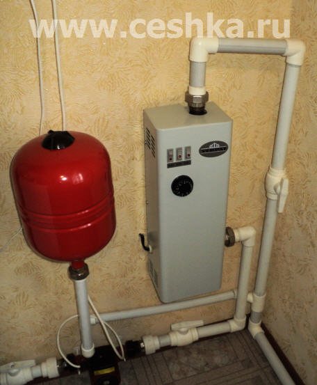
Types of electric boilers
All water heating systems are arranged in the same way. The water heated by the boiler passes through the structure of pipes and radiators and returns for heating. In the electric boiler there is energy conversion from electric to heat, which provides heating of the coolant. Responsible for this process Heating element.
There are two types of installation of a tubular electric heater:
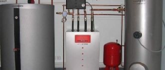
- It can be integrated into the heating system, which simplifies the task. Such an electric boiler can be used as main heating device or auxiliary. But, it should be borne in mind that to create such a device, a pipe of a larger diameter is required than those used in the heating system. In order to avoid having to cut out the electric boiler in the event of a malfunction, it must be made removable.
- Experienced specialists believe that it is more efficient and expedient to create a unit that is located separate from the system. This allows you to make the necessary repairs without violating its integrity, provides better conditions for monitoring its work. This option is also better suited for the installation of additional sensors to increase safety and efficiency heating system. In addition, if it is necessary to replace the device with a boiler designed for a different type of fuel, its installation will not cause problems.
The heating element must be purchased ready-made, choosing the power taking into account the area of the house, the throughput of the system. For heating a house with an area up to 50 sq. m. you need a device with power 6 kW, area up to 80 sq. m. - 12 kW. You can use two heating elements installed in parallel.