
What is a comb for?
What constitutes the functionality and efficiency of a heating system? It must provide a comfortable temperature in all areas of the house and the necessary heating of water. In addition, it must be safe during operation and as maintainable as possible.

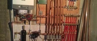
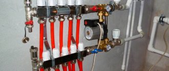
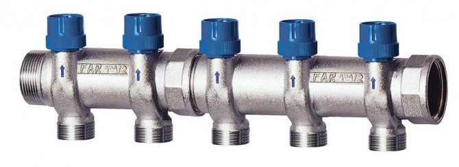
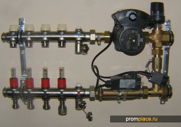
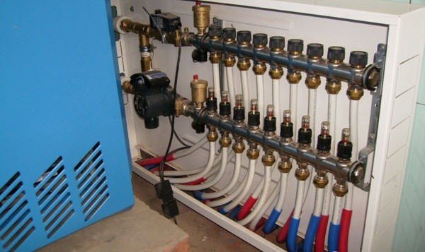
One of the functions of the comb is the ability to turn off the supply of coolant to a separate circuit of the heating system. This allows you to carry out repair work without turning off the heating as a whole
All these conditions of normal operation are helped by a functional element of the collector (beam) heating wiring diagram, which is called a collector or a comb. For example, in the house suddenly, as it often happens, a radiator or pipe joints leaked. If there is a comb, this local problem can be solved without turning off all the heating. It is enough, simply by shutting off the desired valve, to turn off only the area that needs repair.
In addition, one collector, which is installed on the entire heating system of the cottage, will perfectly cope with the function of controlling the heating process. He will also be able to adjust the temperature in every room of the house. The use of this device allows you to control the heating system quite efficiently and simply. At the same time, the costs of manpower and resources are minimized.
How to adjust the comb?
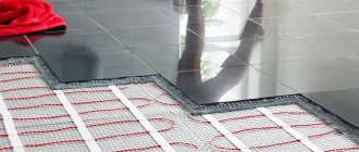
In order for the water underfloor heating to provide a comfortable temperature in all rooms, the distribution unit must be pre-configured. The system is regulated by 2 parameters of the coolant:
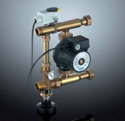
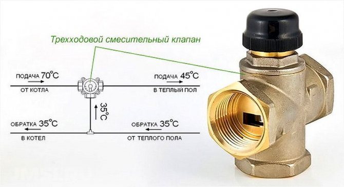
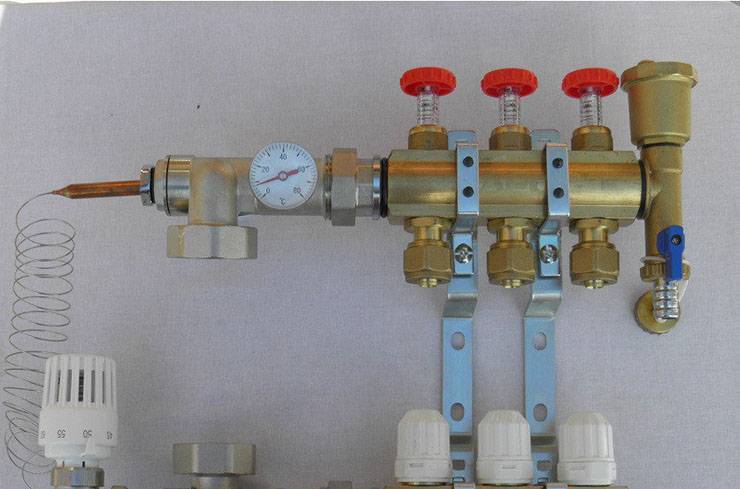
The first parameter is set on the 3-way mixing valve. This can be done manually by setting the required water temperature by turning the adjusting wheel. But more often a thermostatic head with a remote sensor and a capillary tube is involved in the circuit, so the water temperature must be set on it. The sensor is tightly attached to the manifold.
The quantitative adjustment of the comb can be carried out both manually and automatically. By rotating the cap on the valve of each circuit and looking at the readings of the flow meter, you should achieve the design water flow, if you know it. If not, then it will feel like adjusting within a few days.
Automatic adjustment involves the installation in place of the caps of special servo drives, remotely interacting with thermostats in all rooms. Then the comb with the pump will deliver as much coolant into the heating circuits as is needed at the moment. Servos on all taps will control the flows at the command of the thermostats.
Both the distributor and the regulator
At its core, a manifold is a centralized unit that allows the coolant to be distributed to its destination. In the heating system, it performs no less important function than a circulation pump or the same boiler. It distributes the heated water through the mains and regulates the temperature.
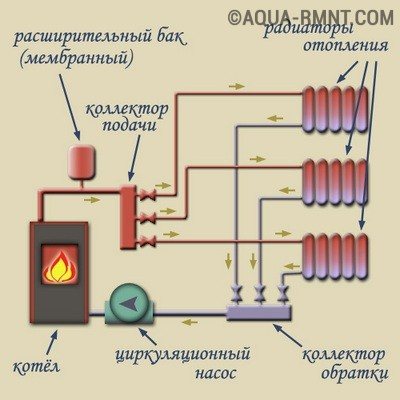
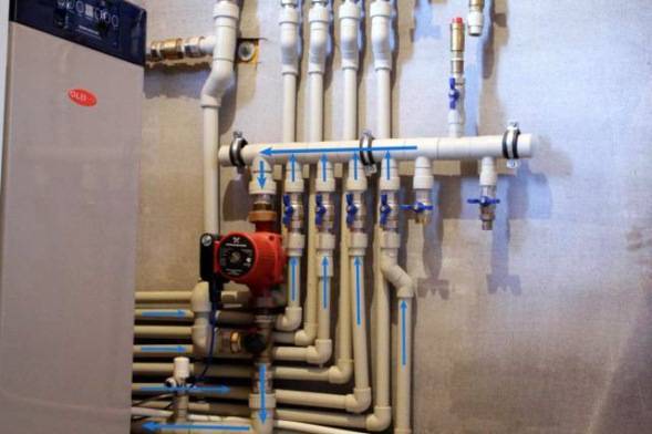
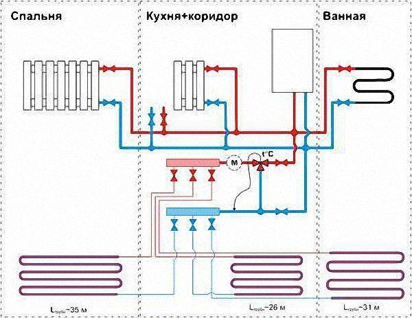
This diagram shows the general principle of operation of a collector block, consisting of two combs: through one, the coolant is supplied to the system, and through the second it is returned
This unit can be called a temporary coolant storage. It can be compared to a barrel filled with water, from which the liquid flows out not through one hole, but through several. In this case, the pressure of the water flowing out of all the holes is the same.This ability to provide a uniform distribution of the heated liquid at the same time is the main principle of the device.
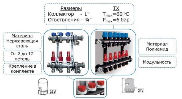
Externally, the collector looks like a two-comb assembly, most often made of stainless steel or ferrous metal. The outputs available in it are designed to connect heating devices with it. The number of such terminals must correspond to the number of serviced heating devices. If the number of these devices increases, the node can be increased, so the device can be considered dimensionless.
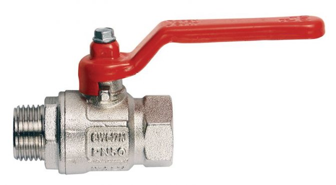
In addition to the terminals, each comb is equipped with locking mechanisms. These can be of two types, installed at the outlet:
- Cut-off. Such taps allow you to completely stop the supply of coolant from the general system to its individual circuits.
- Adjusting. With the help of these taps, the volume of water supplied to the circuits can be reduced or increased.
The manifold includes water drain and air release valves. Here it is most convenient to arrange the measuring equipment in the form of heat control meters. In this case, everything that is necessary for the effective operation of this node will be in one place.
Why does the manifold block include two manifolds? One serves to supply the coolant to the circuits, and the second is responsible for collecting already cooled water (return) from the same circuits. All elements necessary for effective functioning must be on each of the combs.
How to assemble a comb for underfloor heating
I must say that assembling the comb with your own hands is a very real task. If you have installed the heating system in your house yourself, then you have enough skills to assemble this unit. Moreover, factory-made combs are supplied in a set and they are accompanied by installation instructions with diagrams and explanations. An example of such a scheme is presented below:
At the moment, distribution units are made of the following materials:
- brass;
- stainless steel;
- plastic (polyamide).
Factory comb made of plastic is truly a godsend, its cost is much less than that of metal "brothers". Moreover, in practice, it functions no worse, in any case, there are very few negative reviews about it. The assembly of a distributor from any material consists in connecting the comb sections to each other, screwing a mixing unit from a pump with a valve to them, installing thermometers, taps and air vents. The finished manifold can be installed in place and pipes can be connected to it.
For those who do not wish or cannot purchase a plastic collector, there is another option - to solder the comb of polypropylene pipes and fittings on their own. To do this, you need to stock up on the required number of tees and sections of PPR pipes of the same diameter. Since the tees cannot be connected directly to each other, pipe blanks should be cut, which will serve as connecting nipples.
If you managed to solder the number of tees you need, it remains to securely attach them to the wall, and then beat the rest of the piping around them: pump, valve, taps and other parts. We must try to ensure that massive parts are attached to the wall on their own, and not load the distributor with their weight. True, a hand-made comb will be devoid of flow meters and control valves, but if necessary, they can be purchased and installed additionally.


How to install correctly
The installation of the collector is carried out depending on the location of the main pipes of the boiler, as well as on the configuration of the pipelines for each individual room. As a rule, the point of installation is chosen a point equidistant from each final branch of the pipeline to the longest ones.
If it is supposed to heat a sufficiently large number of adjacent rooms, then it is more expedient to foresee the presence and location of several units for separating the coolant in advance. Compliance with this condition will ensure the optimal hydraulic mode of operation of the entire system as a whole.
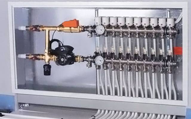
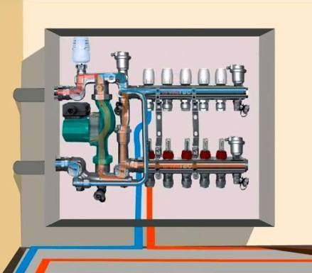
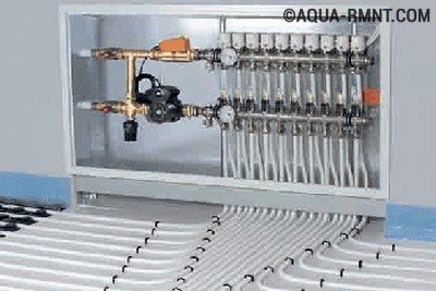
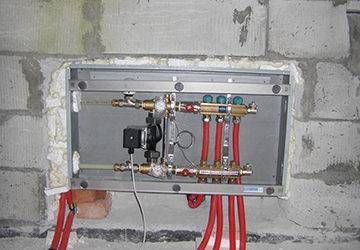
Manifold cabinet
Most often, collectors with two outputs are used, but in some cases it is required to install mixing units for four or more, up to twelve units. In this case, the entire structure is large enough, so it is very often "hidden" in a manifold cabinet, which is specially equipped for this with their own hands. It is a metal box in which the collector itself and all its components are placed (pump, mixing units, loop outlets, etc.)
It can be closed or open. Also both built-in and hinged. The first ones have a front side decorated to match the overall interior. And the latter, in most cases, have a printed powder coating.
The dimensions of the cabinet directly depend on the size of the collector, taking into account all additional elements. The optimum mounting height is about half a meter from the floor. It is not entirely rational to fix the cabinet below, since later it will not be very convenient to insert the pipes into the collector itself.
In addition to functional advantages, such an installation will add aesthetics to the interior of the room, and will subsequently protect a rather expensive installation from accidental and unwanted mechanical damage.
Basement
When it is planned to use the collector simultaneously on two floors of a house in which there is a basement, then most often it is he who is determined by the location of the comb.
Device and principle of operation
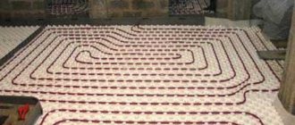
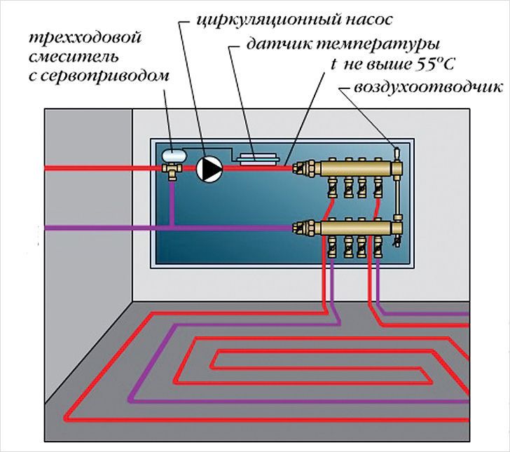
In the process of laying out the pipes of the heating circuits, their ends from all rooms converge in one place, where the underfloor heating comb is connected to them. It is a distribution and mixing unit, whose task is:
- reduce the temperature of the heating medium coming from the boiler. To supply to the floor system, water is needed with a temperature of no more than 45 ° C, and the heat generator rarely heats the coolant to such a low threshold. Usually at the entrance to the comb the minimum is 55 ° С;
- provide the required amount of heat for each room. Here the distributor comb works as a regulator of the heat energy release, controlling the flow rate of the heat carrier in each circuit.
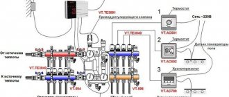
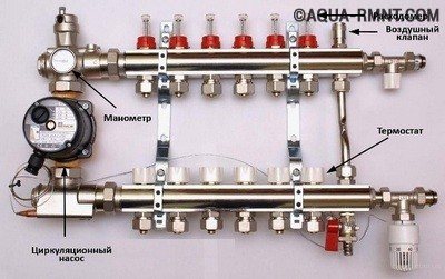
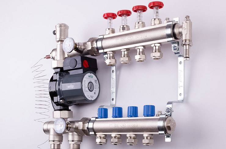
The distributor for underfloor heating visually resembles large heating combs installed in heating points. It also has 2 horizontal collectors - supply and return, to which consumers are connected, in our case - heating circuits. From the ends, the coolant is supplied to the collector pipes from the main line - from the boiler room. A typical comb connection diagram is shown in the figure:
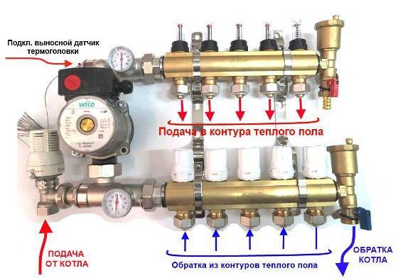
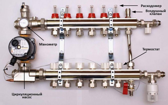
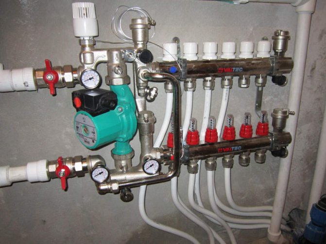
To regulate the amount of water leaving in each of the circuits, valves with a pressure rod are installed on one of the collectors. The adjustment can be done both manually and using various automation tools, for example, servo drives. To control the amount of coolant, the outlets from the second collector are equipped with flow meter flasks. The comb device is shown in detail in the diagram:
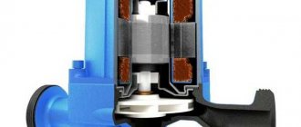
It can be seen here that in addition to the elements listed above, the circulation pump is an important part of the manifold. Without it, not a single circuit will be able to work, since it is the pump installed between the two collectors that is responsible for the circulation of the coolant through the pipes
The very principle of operation of the comb is as follows. Hot water coming from the boiler enters all circuits in the required amount, prompted to move by the pump.Moreover, the coolant moves in a circle until its temperature drops below the set one. Since the temperature of the water is controlled by the sensor of the three-way valve, after its decrease, the valve will begin to open the way for water from the boiler line, mixing it with the cooled coolant.
When the temperature in the manifold rises to the set limit, the three-way valve will close the line again. The pump of the comb of a warm water floor works non-stop, providing circulation inside the system, independent of other heating networks in the house. To empty the unit, the design of the comb provides for the installation of drain valves. In order to release air from this separate system, the circuit can be supplemented with automatic air vents.
Launching a water-heated floor
The commissioning of a water underfloor heating consists of several stages. The first step is to start the circulation of water through the circuits and expel the air. For this you need:
- If the system is filled with water, then check that all taps are open so that circulation is possible not only inside the underfloor heating circuit, but also outside in the system, because the mixing valve will try to take hot water from the system.
- Set the knob or thermostatic head of the mixing valve to the minimum temperature position.
- Start the underfloor heating circulation pump. In this case, it is better that the boiler is turned off, because the boiler pump will interfere with operation.
- If manual air vents are installed on the end elements of the manifold, bleed the accumulated air from time to time.
- Check on the flow meters that the circulation goes through all the circuits. Often from the first floor, a branch goes to the second floor to the bathroom. If there is no automatic air vent at the top, then it will be difficult to expel air from it. To do this, you need to close the rest of the circuits and set the pump at maximum speed in order to let all the pressure up. If this does not work, you need to stop the pump and drive the circuit with tap pressure. To do this, close the supply valve to the collector, all collector circuits are closed, except for the upper one, and abruptly open the drain valve on the return collector. The water escaping under pressure will displace the air; it may be necessary to open the system make-up from the water supply.
- Bleed air from the entire heating system. Part of the air from the underfloor heating circuits will get into it.
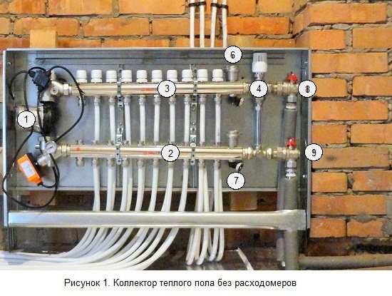
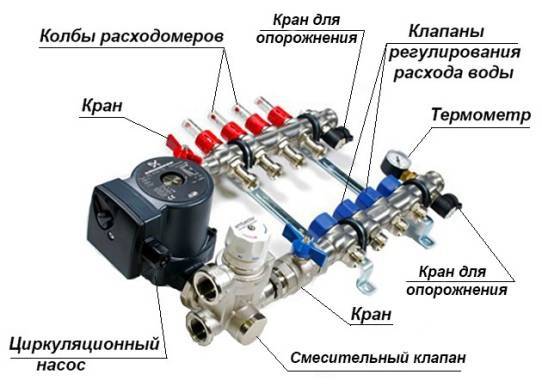
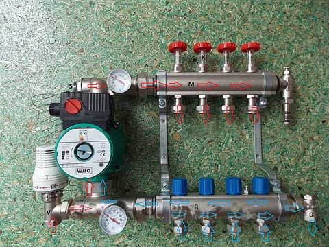
Figures 1 and 2 show, respectively, manifolds without flow meters and with flow meters. On them the corresponding elements are indicated by numbers:
1 - circulation pump; 2 - supply manifold; 3 - return manifold; 4 - mixing valve; 5 - flow meters; 6 - air vent; 7 - drain valve; 8, 9 - supply and return pipelines from the boiler, respectively.
Collector placement rules
If we are talking about a private house consisting of several floors, collectors are placed on each of them. They will be responsible for heating the rooms on the floor on which they are installed. This helps to save on fuel costs. These devices make the circuit of each floor autonomous. If there are rooms on one of the floors that are not used during the daytime, their temperature can be temporarily reduced.
However, the temperature regime can be adjusted not only on the floor as a whole. Sometimes it is enough to turn off only one room or even just one radiator. This procedure will not affect the operation of all other heating devices in any way. In addition, heating of each of the radiators occurs evenly, since it receives the coolant through a separate pipe that fits exactly to it.
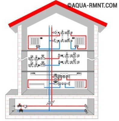
If the heating scheme is drawn up on a multi-storey building, you should place your collector on each floor, then it will be responsible for the operation of heating devices on this particular floor.
Such a heat supply system may seem like a rather expensive structure, but in the process of operation, the benefits from its use become obvious. It pays for itself and the costs incurred at the installation stage will no longer seem excessive to you.
If there is a need for urgent repair of any of the circuits or any specific heating device, then the benefits of using a collector become obvious. The repairman will simply disconnect the damaged area or device from the coolant flow by turning off the valve at the outlet of the switchgear.
Of course, the use of this heating system has not only advantages but also disadvantages.
Of course, the pleasure of living in a warm place and being able to save on fuel and possible repairs is not cheap. But over time, all your upfront costs will pay off.
For example:
- Significant costs at the stage of installation. Plain pipes are cheaper than high strength steel products, which are required to make the manifold. This must be taken into account, and then add the cost of the locking mechanisms used in the circuit. With an increase in the number of circuits, costs also increase in direct proportion.
- The need for a circular pump. Such a pump is simply necessary for the operation of the beam system, and this entails an increase in energy costs.
- Additional expenses. If a separate branch is suitable for each of the heating devices, you will have to spend money on additional pipes and pay for their installation.
The increase in the volume of work will lead to the fact that they can be delayed for a long time. But during operation, this system will be more reliable and more efficient.
Comb installation rules
The place for placing the collector block must be determined at the design stage of the house. As mentioned above, if it is a multi-storey cottage, then such nodes should be provided on each of the floors. It is best to prepare special niches for them, which are located above the floor level.
However, if it was not possible to find a place for the node in advance, you can install this unit in any room in which it will not interfere with anyone: in the storeroom, in the corridor or in the boiler room. If only there was no excess moisture in this place.
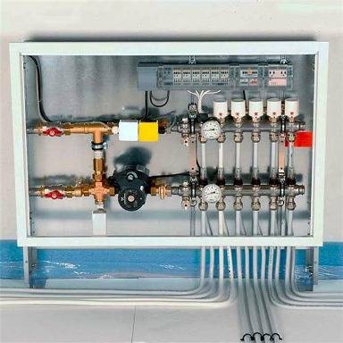
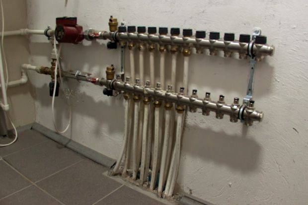
To keep the unit out of sight, you can place it in a special cabinet, which manufacturers of locking mechanisms offer their customers. The body of such a cabinet is made of metal. It is equipped with a door, and there are holes for heating pipes in its side walls. Sometimes the collector group is simply placed in a niche or on a wall, securing the combs with special clamps.
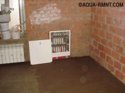
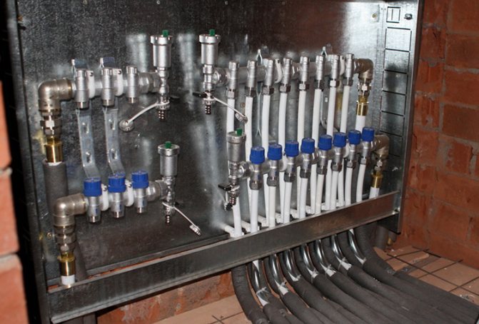
This comb is placed in a specially equipped place for it. As you can see, it looks quite aesthetically pleasing, and most importantly, access to this node will not be difficult.
The pipes that extend from this switchgear are located in the walls or in the floor, and then connected to the radiators. If the pipes are in the floor screed, the heaters must be equipped with an air vent or air tap.
Control elements
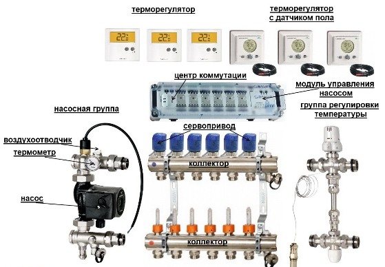
Setting up the underfloor heating collector is impossible without special devices. With their help, the optimal heating mode of the system is established, the flow of water in the pipelines is regulated. Each of them has a specific function.
- Water temperature sensor
Installed on the inlet and outlet pipes of the device. These devices do not affect the operation of the system, but indicate the current heating value. The difference in values can be useful in calculating work efficiency. They also serve as an indicator of a violation of the heating mode.
- Central thermostat with servo mechanism and sensor.
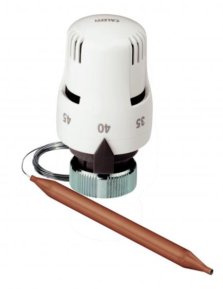
It is mounted on the inlet of the inlet manifold and connected to the return pipe with cooled heat carrier.The temperature sensor is housed in the comb body. There is a rotary knob on the thermostat body, with which the required temperature level is set. From the sensor, the device receives readings about the degree of water heating. Depending on this, the flows of cold and hot heat carrier are regulated.
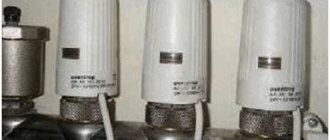
- Servos on the inlet manifold nozzles
By the principle of operation, they are completely similar to the thermostat, but with minor additions. With their help, the volume of water flow is regulated for each circuit of the water floor. This can be done manually or automatically, depending on the model. For the latter, servo drives with built-in temperature sensors are used, which can be connected to a common remote thermostat.
- Flow meters
Devices optional for installation, which, however, can become effective elements for manual control of the operation of a water heated floor. They are installed on the return manifold pipes and are shut-off mechanisms with a glass bulb.
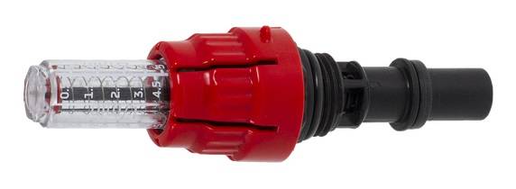
When the head is turned on the body, the stem in the device changes its position. This affects the volume of fluid passing through it. For clarity, a measurement scale is applied to the surface of the flowmeter, indicating the water flow rate l / min.
Purpose of the device
Underfloor heating substrate purpose and varieties
The main function of this device is the efficient distribution of the coolant along the heating main due to the coordinated operation of the built-in thermostatic and regulatory fittings
The presence of flow controllers is very important since the pipe loops are of different lengths. In accordance with the laws of physics, if an equal volume of coolant enters a pipe of greater and lesser length, then at the end of a long branch, the liquid that heats the floor will become cooler than that which will be at the exit from the shortened branch
First of all, this is reflected in the quality of work - a water heat-insulated floor without a comb, regardless of the connection scheme, acquires "streakiness". Another negative point may be a situation in which the coolant does not enter the elongated circuit at all. This is due to the fact that it has an increased hydraulic resistance, as a result of which water will flow through a shortened (with reduced resistance) pipe. The flow controllers help to balance the level of the coolant entering the system so that the contour separation of the coolant becomes proportional to the length of the elements.
Comb selection criteria
The first step is to pay attention to what material this structure is made of. The most popular collectors are made of brass, which are produced by casting
In this case, a strong and durable part is obtained, but at the same time it is very expensive.
Welded products made of stainless steel are cheaper. The comb turns out to be quite strong, but this material can be susceptible to electrochemical corrosion.
Products made of high-quality plastic material are considered a budget option. In terms of their qualities, they are not inferior to metal parts.
The next criterion for choosing a collector is the number of production branches. It is best to choose a product with taps equal to the number of heated circuits so that you do not have to drown out unnecessary holes.
Further, the technical equipment of the collector is taken into account for automating and regulating the temperature of the coolant. If you need a comb that will serve you for a long time, then brass is your option.
If you need a comb that will serve you for a long time, then brass is your option.
Today there are combs that can be connected to thermostats and programmable controllers. With their help, it is much easier to carry out adjustment, as well as to control the quantity and quality of the coolant in the circuits.
How to build a collector yourself
You can buy a ready-made uze, choosing one that would approximately meet the needs of your home. But getting an exact match is tricky. Therefore, it is better to make a heating comb yourself. Let's figure out what is needed for this.
Planning phase
There are a number of parameters of the heating system of a house that you should know when building a block.
- The number of circuits through which the heated water will pass.
- The number and technical characteristics of the heating equipment included in the scheme.
- Additional equipment involved in the installation. This refers to pressure gauges, thermometers, taps, storage tanks, valves, pumps, etc.
It is also necessary to provide for the possibility of increasing the load, if over time it is necessary to build in elements that were not taken into account in advance. This can be, for example, solar panels or a heat pump.
It is necessary to foresee in advance not only the number of circuits operating in the heating system, but also additional equipment that will be included in the general scheme
Determining the construction of the block
The design of the future node depends on the connection point of each of the circuits. After all, there are some connection nuances that cannot be ignored.
- Boilers (electric and gas) must be connected to the top or bottom of the comb.
- The circulation pump should be connected from the end of the structure.
- Solid fuel units and indirect heating boilers also need to be cut from the end.
- The supply circuits of the heating system are connected from below or from above.
For clarity, it is necessary to make a drawing of the future compact and neat unit. This will help determine the amount and types of materials that we need. All the necessary dimensions, threaded connections with a thread pitch are applied to the drawing. All contours should be marked in order to be guided by the drawing when connecting.
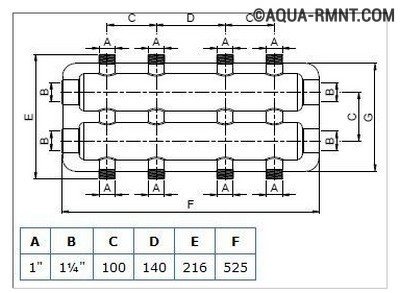
This drawing shows a four-way manifold. You can skip the drawing and limit yourself to a sketch, but do not forget to put all the dimensions necessary for work on it.
The distance between the nozzles of both combs should be between 10 and 20 cm. These are optimal parameters for service. The distance between the feed and return combs themselves should be within the same limits.
Sequence of work
For the manufacture of both dies, not only round but also square pipes can be used. The sequence of work performed is as follows:
- In full accordance with the parameters indicated in the drawing, we purchase all the necessary materials.
- According to the drawing, we make a connection by welding pipes, taking into account their subsequent functions. Welding points should be cleaned with a wire brush and degreased.
- Testing a homemade node is a necessary stage of work. To do this, all pipes are hermetically closed except for one through which hot water is poured into the system. Let's take a good look at all the joints: they shouldn't leak.
- The collector can now be painted and dried thoroughly.
- Next, pipes, locking mechanisms and control equipment should be connected to it.
After that, the device is ready for use.
This one will differ favorably from purchased products in that it was built taking into account the needs of a particular house, and this is very important for its further operation. Of course, a high-quality and functional device can only be obtained if the master knows how to handle a welding machine and a locksmith's tool.

In order for a homemade manifold block to work more efficiently than a purchased one, the craftsman needs to be able to handle both welding equipment and locksmith tools
You can learn how to make a polypropylene manifold by watching this video:
Heating of premises by means of water-heated floors is considered one of the most effective ways in terms of saving energy resources and even distribution of heat. As you know, heating is carried out by means of pipes with a heat carrier laid in the screed. Each room is a separate closed loop, or even several. Their work is controlled by one common unit - a comb for a warm floor. Information on how this unit functions, the nuances of its assembly and regulation is offered to your attention in this article.
Working with collector flow meters
Hydraulic balancing of underfloor heating loops consists in regulating the flow rate in each coil. Depending on the length, a different amount of incoming heat carrier may be required in order for it to cool down exactly to the calculated value when passing through the loop. Quantitatively, the required flow is determined as the ratio of the heat load on the loop to the product of the heat capacity of water or other heat carrier by the temperature difference in the supply and return: G = Q / s * (t1 - t2).
You can often find recommendations to determine the flow rate of the coolant according to the performance of the circulation pump, that is, to divide its supply in proportion to the ratio of the lengths of the loops. Such advice should be avoided: in addition to the fact that the length of each coil is difficult to calculate, one of the most important rules is violated - to choose equipment parameters based on the needs of the system, and not vice versa. Attempts to distribute the flow in the described manner almost always lead to the fact that the flow in the loops differs significantly from the calculated values, which makes further adjustment of the system impossible.
The very same adjustment of the flow with flow meters is quite simple. In some models, the throughput is changed by turning the body, in others - by rotating the stem with a special key. The scale on the body of the flow meter indicates the flow rate in liters per minute, you just need to set the appropriate position of the float.
Almost always, when the throughput of one flow meter changes, the flow rate in the remaining loops changes, therefore, the adjustment is carried out several times, sequentially calibrating each branch. If such changes are especially pronounced, this indicates a lack of throughput of the control valves through which the collector is connected, or about too low performance of the circulation pump.
Practical tips for setting up underfloor heating systems
- Technical support
- Articles
- Practical tips for setting up underfloor heating systems
# warm floor # built-in heating # design # installation # commissioning
Loop balancing

The installation of the underfloor heating system is undoubtedly a responsible operation, however, how comfortable it will be to use the finished heating system depends most often on competent commissioning. Setting up an underfloor heating system is not as difficult as it might seem at first glance.
Generally speaking, setting up a heating system consists of three stages. This is balancing the underfloor heating loops, setting the pump and mixing unit and setting the controller, if available.
This article will discuss the methods that are used to balance underfloor heating loops. First of all, it is worth noting the main misconceptions that occur with such a balancing.
- Sometimes you can hear that it is possible to correctly balance the system only by calculation, that is, by calculating the resistance of all loops, calculating the tuning position of the control valves, install it on the manifold. Of course, a project with a competent hydraulic calculation speeds up the setup process and protects against installation errors. But, nevertheless, the underfloor heating system can be set up without theoretical calculations, although this will take more time.
- It is also considered a delusion that the flow rate in all loops should be the same. In fact, the flow rate primarily depends on the thermal power that each particular loop transfers to the room.
- You can often hear that the underfloor heating system does not need to be balanced at all, and the water consumption will level out by themselves due to the operation of thermostats, controllers and other automation elements. This statement is also not true. The fact is that sooner or later the moment will come when all loops of the heated floor will open to the maximum, and the distribution of the coolant should be such that all the water does not go into one loop, but is evenly distributed throughout the heated circuit.
So, the heating system is filled and tested, the boiler is running, a hex key is in the hands, giving off a pleasant weight, turning into an itch of impatience. Where do you start?
First of all, it is worth deciding on the goals and objectives of balancing.
The task of balancing is not to set the required flow rate for each loop, but to set the ratio of flow rates by loops or the balance of flow rates. Finally, the costs are set during the setting up of the pumping and mixing unit. At the same time, by changing the total flow rate through the collector, the ratio of the flow rates through the loops is maintained.
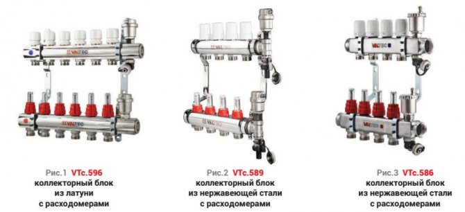
Balancing also differs depending on whether the manifold block has flow meters. Manifold blocks VTc.596 (fig. one
), VTc.589 (
fig. 2
), VTc.586 (
fig. 3
) are equipped with flow meters that significantly speed up balancing and allow it to be carried out without turning on the boiler, since they show in real time the water flow in each direction.
The distribution of costs must be carried out in such a way that the ratio of the costs for the loops and the ratio of the required heating capacities coincide. For this, it is desirable to know the required heat loads on the hinges. But even if the required loads are not known, then the costs can be set in proportion to the lengths of the loops. As a rule, this approach does not give a large error, since loops with long lengths also have high powers.
Balancing starts by choosing the longest loop (or the loop with the highest power, if known). The control valve on this loop opens to the maximum position, and the flow rates of all other loops will be set relative to it.
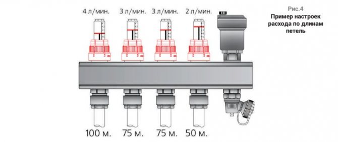
Take a manifold with four loops as an example. Let us assume that the lengths of the loops are as follows: 100, 75, 75 and 50 m.
In this case, the tuning starts with the first loop, which is 100 m long. It opens to the maximum. Suppose that with the valve fully open, the flow in this loop is set at 4 l / min.
The water consumption for the second and third loops should be: (75/100) 4 = 3 l / min.
The water flow in the fourth loop should be: (50/100) 4 = 2 l / min (fig. four
).
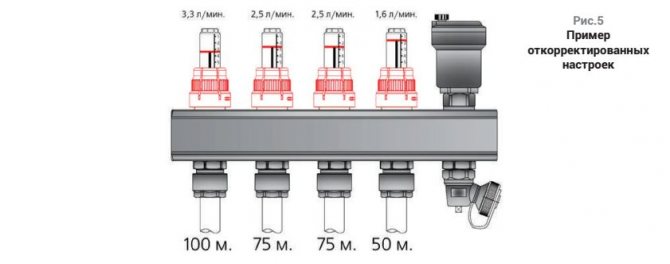
It may happen that when adjusting the third loop, the flow rate, even with a fully open valve, is set at 2.5 l / min and does not reach the prescribed level of 3 l / min. This means that the loop has a higher hydraulic resistance than the second loop of the same length (more bends, rolls, lead-in sections). In this case, balancing can be carried out only with the boiler turned on and at least with a minimum heat output in the room. The first loop is at (100/75) 2.5 = 3.3 L / min, the second loop is at 2.5 L / min and the fourth loop is at - (50/75) 2.5 = 1.6 L / min (fig. five
).
After all the costs have been set, the balancing of the loops can be considered complete and you can proceed to setting up the pumping and mixing unit.
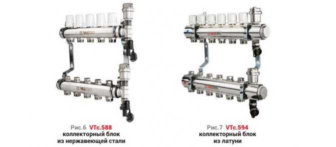
If you configure manifold blocks without flow meters, such as VTc.588 (fig. 6
) or VTc.594 (
fig. 7
), then the costs in the loops can be judged only by indirect signs.
In this case, balancing can be carried out only with the boiler turned on and at least with a minimum heat output in the room. It is desirable that the outside temperature is below +5 ºС. The premises should not have open windows and any significant heat release (a working fireplace, etc.). Tuning, as in the previous case, begins with the definition of the longest loop.
Then the system must be left to warm up for several hours until the temperature in the loops stabilizes, after which it is necessary to evaluate the correctness of the setting made.
- The correctness of the setting is determined in one of the following ways:
- by the temperature of the water in the return pipeline;
- by the average floor temperature.
Determination of the correct setting based on the water temperature in the return pipe
Heating medium flow, power and temperature difference between supply and return pipelines are interrelated. If you reduce the flow rate of the coolant in the loop, then the temperature difference will inevitably increase. It is by this dependence that you can determine the correctness of the setting.
If all loops have the same temperature difference between the supply and return pipelines, this will mean that the water flow rate in all loops corresponds to the current power. And since the temperature in the supply manifold is the same for all loops, the temperatures can be equalized only in front of the return manifold.
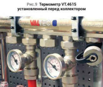
The most convenient way to estimate the temperature is with a special thermometer, such as the VT.4615 (fig. eight
). Such a thermometer is inserted between the pipe and the return manifold through a Eurocone connection (
fig. nine
).
The reference temperature is determined on the longest loop, then all other valves are adjusted depending on the deviations from this temperature. If the temperature on the loop is lower than on the reference one, this means that the flow rate in this loop is also low, and the valve should be slightly opened. If the flow, on the other hand, is higher, then the valve should be closed. Then, after half an hour, this operation should be repeated until the water temperatures in front of the return manifold are equal for all loops.
Determining the correct setting based on the average floor temperature

The previous method is quite simple, but does not take into account the finish of the floor. If the rooms have different floor coverings, then in order for the temperature of the floor surface in these rooms to be felt as the same, it is necessary that the costs for the hinges take this factor into account.
It is possible to take into account the finish coat by measuring the temperature of the floor surface in different rooms and equalizing the water flow in different directions so that the average temperature of the floor surface in different rooms is the same. You can measure the floor temperature in different ways: with contact thermometers and pyrometers (fig. 10
).
The valves are adjusted in the same way as in the previous case. The valve serving the loop, the floor above which has a temperature higher than in other rooms, is closed and vice versa - at low floor temperature, the valve opens.
It is worth noting that you need to measure the floor temperature at least at six points: above the pipes, between them, at the beginning of the loop, in the middle and at the end of the loop, and take the average value.
When the temperature of the floor surface in all rooms reaches close values, the setting can be considered complete.
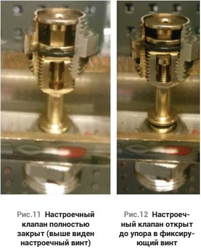
In order to protect the setting of the valves from unauthorized interference, the VTc.594, VTc.588 manifolds have a mechanism for fixing the set position. To fix the setting, it is necessary to tighten the fixing screw up to the stop (fig. 11, 12
). The screw is inside the hexagon. This screw limits the opening of the valve to its current level and prevents it from opening any further. However, it allows the valve to be completely closed. Thus, after adjustment, all the fixing screws can be tightened up to the stop, while in further operation, individual hinges can be closed with the same valve. Further, in order to re-configure this loop, you just need to open the valve all the way.
As you can see, setting up loops is a fairly simple operation, especially if you use convenient equipment for this. Setting up a pump-mixing unit (FNU) also does not raise questions for most installers.Some of the features of configuring the NSO will be discussed in a separate article.
Author: Zhigalov D.V.
Print article: Practical tips for setting up underfloor heating systems
"Whirl
© Copyright holder LLC "Vesta Regions", 2010 All copyrights reserved. When copying an article, a link to the copyright holder and / or to the site www.valtec.ru is required.
Installation of a comb in the heating system and its calculation
Comb in the underfloor heating system
The installation location of the distribution manifold in the heating system depends on its purpose. Most often it is used to organize multi-circuit heat supply. However, in addition to this, it is an indispensable element of a water-heated floor.
Before proceeding with the installation, you should calculate the heating manifold. The main task of this process is to evenly distribute the pressure across the heating circuits. If the system is a complex circuit of highways, it is recommended to make a calculation using special programs. For a simple system with up to 5 contours, the principle of equal sections can be applied.
N0 = N1 + N2 + N3 + N4
Where N0 is the diameter of the collector, N1, N2, N3, N4 are the cross-sections of its outlet pipes.
The same calculation scheme is used when making a do-it-yourself heating comb.
It is important that the dimensions of the inlet and outlet headers match. It is noteworthy that the standard device of the heating comb has no requirements for its shape.
Those. it can be either round or square. The basic principles of installing collector heating are as follows:
- To improve circulation, it is recommended to install pumps for each circuit. At the same time, the distribution manifold of the heating system should not provide synchronization of the pumps;
- If the unit is located in a boiler room, the installation of a protective box is optional. The exception is the installation of a polypropylene heating comb in the underfloor heating system;
- To adjust the volume of the coolant, it is necessary to install control valves on each inlet and outlet pipes - inlet valves and balancing flowmeters;
- When planning the installation of a heating manifold, it is necessary to provide for the presence of a safety group on the distribution unit.
An example of a heating manifold installation diagram
It should be remembered that these are only general recommendations that can be changed and supplemented depending on the specific parameters of the heating system.
In addition to these rules, experts advise taking into account the difference in the length of the circuits when calculating the heating comb. It is recommended to draw up the scheme so that their length is approximately equal.
To reduce energy consumption, a mixing unit can be installed in the heating comb device, which, in turn, will reduce heating costs.
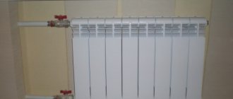
Appointment of the heating manifold
Heater manifolds for heating are installed with radial piping. They are needed in order to distribute the coolant flows over different circulation rings. For example, the house provides for both conventional heating by means of batteries and underfloor heating. At the same time, there is a need to maintain its own temperature in each room. And it also happens that in some rooms you need to completely turn off the heating. In the summer, for example, you don't need to heat the house, but a heated towel rail and underfloor heating should work in the bathroom.
When the house has already been built, the do-it-yourself waterproofing of the basement is done from the inside, which imposes some restrictions.
It all comes down to a simple installation of thermal insulation on a vapor barrier.
To stop circulation, you need to twist the flow meter on the return line of the heating system comb or completely shut off the thermostatic valve. During the heating season, to maintain the temperature at the required level, it is necessary to install thermostats in the required rooms.The thermostat is wired to the actuator and commands it to close or open the thermostatic valve. There are thermostats that are connected to the servo drive by means of radio waves through a special converter.
Features of product installation
When installing this design, it is necessary to take into account a number of rules and features. Typically, the collector is installed on a wall, in the middle or closer to the floor. For this, it is best to use a special manifold cabinet, which gives a more aesthetic appearance to the structural unit.
Holes must be drilled in it for suitable piping. The comb is attached so that it is possible to bleed air from the heating circuits. This will allow you to easily carry out repairs in the event of an accident.
The length of the contours should be approximately the same to make it easier to adjust. This is done according to two indicators: the flow rate of the coolant and its temperature. For this, a flow meter and temperature sensors are built into the circuit.
An important condition when installing underfloor heating is that the total length of each circuit should not exceed 60 m.Otherwise, it will be difficult for the coolant to overcome the hydraulic resistance in the pipelines
When creating a warm floor, a separate heating branch is laid in each room.
This is due to the fact that there are restrictions on the length of one branch, as well as ease of installation.
The distribution of the coolant from a single boiler flow to each branch takes place in a special unit called a collector, or a comb for a warm floor.
With your own hands, you can make an analogue of a factory collector, which will perform its functions no worse, but for less money. What you need to buy, how to properly assemble and assemble in practice.
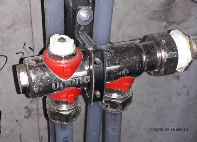
Two-way valve design
In the installation scheme for underfloor heating, the valve is installed directly in front of the comb. It is connected to a temperature sensor, which is located at the return manifold of the coolant. In addition, the distribution unit diagram includes:
- circulation pump;
- balancing valve;
- check valve.
The check valve is part of the manifold
At the beginning of the heating process, the device is in an open state, and the heat carrier enters the collector. The valve remains open until the water temperature reaches the operating value. As soon as this happens, the tandem "sensor + thermal head" will close it, and the coolant will stop flowing from the heating boiler.
During this period, the underfloor heating comb pump will independently circulate hot water through the heating circuits. In this case, the coolant will gradually cool down, and when its temperature drops below the operating temperature, the valve will open again.
Correct mixing of hot and chilled water occurs due to a balancing valve that regulates the volume of the waste heat carrier.
Selection Tips
When buying a factory comb, you should pay attention to its complete set. In addition to the above elements, a safety group must be present - a bypass, a safety valve and an air vent. The standard collector for icma underfloor heating is not equipped with such elements. Therefore, you should purchase them separately. In the event of an unexpected increase in temperature or pressure, these components stabilize the system parameters to optimal values.
You should also pay attention to the cost of the product. A cheap comb for underfloor heating can be made from a copper alloy that is not mechanically strong. It is best to purchase stainless steel devices.
The following video course will help you completely correctly mount the collector. Click on the banner and get acquainted.
© 2020 prestigpol.ru
How the collector works
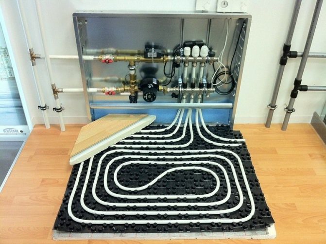
Water floors are laid in various ways, for example, concrete or floor, but regardless of the technology chosen, it is necessary to purchase and install a manifold cabinet.
Note The collector box is recommended to be installed on the wall as close to the middle as possible and most often at the very floor.
In the future, two pipes will be installed into it:
- supply, which leaves the boiler and supplies a hot coolant to the system;
- returnable, which performs an absolutely opposite role: it serves to collect water that has already been used up and has had time to cool down. It is returned back to the boiler and the process is repeated again.
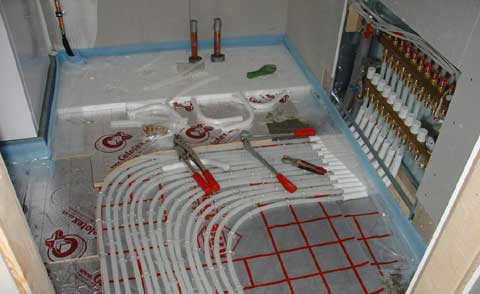
The cyclicity of the process is provided by another built-in component of the system - a circulation pump. One way or another, during the operation of a warm floor, say, during repair work, the system has to be turned off. For this, each of the pipes is equipped with shut-off valves. A plastic pipe and a metal shut-off valve are connected to each other through a compression fitting. Then a comb is connected to the valve, mounting an air vent on one edge, and a drain valve on the other. After assembling the cabinet, proceed directly to the installation. And only with the comb installed on the wall can the pipes of the contour be cut along the length.
Note To ensure the tightness of the connection, the pipes are cut strictly at right angles.
We make the comb ourselves
You can make your own underfloor distributor. You will need the following parts for the comb:
- Brass tee 1/2 inch - 4 pcs.
- Ball valve with 1/2 inch thread - 5 pcs.
- Silicone sealant.
- 1/2 '' plug.
Tees are purchased in such a configuration that the thread is internal on one side, and external on the opposite side.
The assembly is carried out in the following sequence:
- Tees are assembled in one line. To do this, each subsequent tee is connected to the previous one by simply screwing the side of the tee with an external thread into the tee from the side of the internal thread. Thus, a straight pipe with lateral bends is obtained. For proper sealing, it is necessary to treat the joint of the threaded connections with silicone sealant. The sealant is applied only to the tee that has an external thread. After tightening the two parts, the excess sealant is removed with a rag.
- One of the taps must be installed at the inlet of the resulting pipe. The installation is also carried out using silicone sealant.
- On the opposite side of the base a homemade comb is installed with a plug.
- For each side branch the tap is wound.
It turned out a homemade comb for 4 contours of a warm floor. You can make a homemade distributor with any number of taps.
For proper sealing, it is necessary to treat the junction of the threaded connections with silicone sealant.
You can make a comb from plastic pipes
For the manufacture of the distributor, you will need the following materials and tools:
- Soldering iron for plastic pipes.
- Scissors for cutting plastic pipes.
- Adjustable wrench.
- Plastic pipe for heating.
- Plastic tees.
- Metal adapters.
- Plastic sleeve - 4 pcs.
- Ball valves - 5 pcs.
- Plastic corner.
- Silicone sealant.
The plastic pipe is cut into 4 pieces, the length of each piece should not exceed 10 cm. Then, using a soldering iron for plastic pipes, the tees are soldered together using a piece of plastic pipe.
An angle is installed on the extreme tee so that its direction is opposite to the direction of the main branches of the comb. Metal adapters are installed on the side branches, onto which the taps must be screwed using silicone sealant.
On the corner, which was soldered to the main pipe of the distributor, a metal adapter and a Mayevsky valve are installed to bleed air.
The distributor must be installed in such a position that the taps are facing down, and the corner with the air bleed valve is facing up. This arrangement allows you to easily remove the air lock that can form during the operation of the underfloor heating.
Using a soldering iron for plastic pipes, tees are soldered together using a piece of plastic pipe
How to build a collector yourself
You can buy a ready-made uze, choosing one that would approximately meet the needs of your home. But getting an exact match is tricky. Therefore, it is better to make a heating comb yourself. Let's figure out what is needed for this.
Planning phase
There are a number of parameters of the heating system of a house that you should know when building a block.
- The number of circuits through which the heated water will pass.
- The number and technical characteristics of the heating equipment included in the scheme.
- Additional equipment involved in the installation. This refers to pressure gauges, thermometers, taps, storage tanks, valves, pumps, etc.
It is also necessary to provide for the possibility of increasing the load, if over time it is necessary to build in elements that were not taken into account in advance. This can be, for example, solar panels or a heat pump.

It is necessary to foresee in advance not only the number of circuits operating in the heating system, but also additional equipment that will be included in the general scheme
Determining the construction of the block
The design of the future node depends on the connection point of each of the circuits. After all, there are some connection nuances that cannot be ignored.
- Boilers (electric and gas) must be connected to the top or bottom of the comb.
- The circulation pump should be connected from the end of the structure.
- Solid fuel units and indirect heating boilers also need to be cut from the end.
- The supply circuits of the heating system are connected from below or from above.
For clarity, it is necessary to make a drawing of the future compact and neat unit. This will help determine the amount and types of materials that we need. All the necessary dimensions, threaded connections with a thread pitch are applied to the drawing. All contours should be marked in order to be guided by the drawing when connecting.

This drawing shows a four-way manifold. You can skip the drawing and limit yourself to a sketch, but do not forget to put all the dimensions necessary for work on it.
The distance between the nozzles of both combs should be between 10 and 20 cm. These are optimal parameters for service. The distance between the feed and return combs themselves should be within the same limits.
Defining a block design
The design of the collector involves finding the optimal location of the branches and the distance between them. First of all, the following requirements must be considered:
- It is best to connect a gas or electric boiler to the highest or lowest point of the collector. The solid fuel heat generator must be connected to the branch pipe at the end of the distributor.
- The piping leading to the circulation pump is also connected from the end side.
- An indirect heating boiler should be connected on the same side.
- The coolant supply lines are connected from the top or bottom.
- Bends should be located at a distance of 100 - 200 mm from each other (between the axes). The same distance should be maintained between the feed and return combs.
Also, at the design stage, you need to remember that easy access to fittings and devices must be provided.
After major decisions have been made, the collector should be drawn to scale.The drawing will help identify shortcomings and determine which blanks and in what quantity will be needed.
To eliminate the possibility of error, the sketch must be dimensioned, mark the type and diameter of the thread on the nozzles, and, if necessary, indicate the material of all components.