Home ›Engineering systems› Integrated solutions ›Ventilation and heating› Installation of heating and ventilation
You can order the installation of heating and ventilation systems on a turnkey basis with installation by calling in Moscow. Design and supply of heating and ventilation systems in Russia. We ask you to send a written application by email or through the form on the website.
- What is SNiP?
- Heating system installation sequence technology
- Installation of basic types of heating
- Ventilation system assembly sequence technology
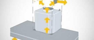
- Ventilation and heating by means of a recuperator
Send an application and get a quote
- Rates
for the installation of engineering systems
The installation of a modern heating and ventilation system implies the presence of special devices for connecting pipes (a soldering iron for plastic - for a plastic heat conductor). When you purchase, you are supplied with a disassembled system, and in addition to pipes, it contains corners, tees, couplings, plugs. You can put it all together with a plan or project drawn up by experts. The parts required to connect the elements of the system are called couplings. They are often in short supply, so it is worth stocking up on them.
"Standard Climate" is a professional climatic company, ready to implement solutions to any problems in climatic and other engineering equipment on a turnkey basis. We will perform a full cycle of work: selection of equipment, design, installation, delivery and maintenance. On the website airclimat.ru you can send an application. Call now: +7(499) 350-94-14
... Submit your application
Definition
The term "axonometry" is originally from Greece and comes from two words: "axis" and "measure". The essence of the term is in the graphic representation of three-dimensional objects by the method of their projection onto a plane.
How the object is projected:
- It snaps to three coordinate axes.
- The so-called picture plane is selected, onto which the object is to be projected.
See: no coordinate axis should be parallel to it.
- All points of the object are projected onto the plane.
Because the picture plane is not parallel to any of the coordinate axes, the projection will have deviations from the actual dimensions of the segments along all axes.
Depending on how the distortions are distributed along the axes, axonometry can be called:
- Isometric... In this case, the distortion is the same along all axes.
- Dimetric... Equal distortion in two axes.
- Trimetric - all distortions have different meanings.
An axonometric diagram of a heating system is just its projection onto a plane that is not parallel to either the walls of the building or its floors. The projection indicates the elements of the system and their main parameters.

Axonometry of water supply, heating, sewerage
According to GOST 2.317-2011, all axonometric diagrams related to sanitary systems of water supply, sewerage, heating are built in frontal dimetric (oblique) isometry with a left coordinate system.
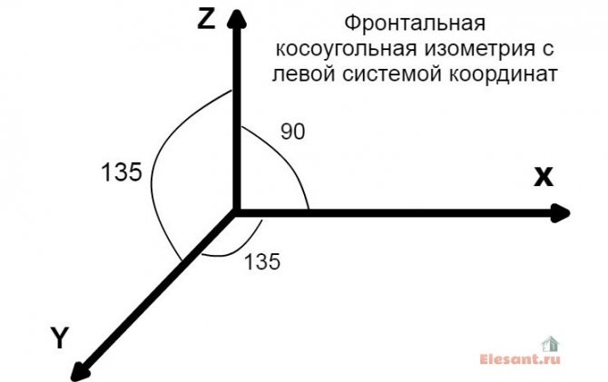
Accordingly, the dimensions along the z and x axes will be without distortion, and along the y axis by half.
What does this drawing have to do with pipes and plumbing, you ask? Now imagine that the planes along the axonometric axes are the walls of your house or apartment. Plumbing pipes, water supply lines, sewerage and heating pipes run along the walls, vertically or horizontally. This means that we can draw pipe paths in axonometry without showing the walls themselves.
This will give very clear drawings of how and where to install the plumbing wiring. Moreover, plumbing fixtures are applied to the axonometric diagram in symbols, pipe diameters are applied, explanations are made, tables on materials and equipment are compiled for the diagrams. As a result, you have in your hands a detailed guide on how to install plumbing fixtures in a house (apartment), practically eliminating installation errors.
Regulatory requirements
They are exhaustively set out in GOST 21.602-2003, which regulates the rules for drawing up documentation for the engineering systems of a building (as well as heating). Let's select from the text of the document the main points that are vividly related to our topic.
Non-specialized provisions
Elements of heating systems are assigned designations that consist of a serial number and markings within this scheme. What specific designations are used?
For some graphic designations, the document refers to the adjacent GOST:
- The pipelines to be routed shall be designated in accordance with GOST 21.206 - 93.
- Designations of check valves, throttles, gate valves, radiators, etc. can be found in GOST 21.205-93.
In addition, among the non-specialized provisions, there is a sequence of additional drawing requirements.
- Elevations are indicated on extension lines or element outlines.
- The axonometric heating scheme can be performed on a scale of 1:50, 1: 100 and 1: 200.
List of designated parameters and equipment
On a self-made diagram, the following should be indicated:
- Pipelines with specified diameters.
- Thermal insulation of pipeline sections. She is depicted graphically.
- The axis levels of all pipelines are fairly zero.
- Pour slopes (obviously where they are needed - in homes and gravity top-fill systems).
- If there are gaps in the horizontal sections of the filling - the size of the sections.
- Supports, hangers and expansion joints.
The fundamental point: in this case, the image is supplied with a shelf-extension, above which the type of element is indicated. The corresponding document should be indicated under the shelf.
- Shut-off valves. And in this case, an extension shelf is used, above which the diameter and type (DU) of the reinforcement are indicated. Below is the catalog item designation.
- stanchions and risers (horizontal sections) with designations.
- Radiators, convectors and other heating devices.
Their main parameters and type must be indicated:
- The number of sections of a sectional radiator.
- The number of sections (pipes) of the register and its length.
- length and number of finned tubes.
- For other heating devices - their type.
- Designations of installations (boilers, furnaces with heat exchangers, heat pumps, elevator units, circulation pumps for heating, etc.).
- Embedded devices (oil cups for temperature control and taps for the installation of control valves allowing pressure measurement).
- The devices themselves for recording the parameters and measuring the heat system.
Curious: GOST allows for multi-storey buildings to draw up a detailed diagram only for the underground part of the building. In this case, the riser wiring diagram and, if necessary, the attic wiring diagram are performed separately. The instruction is associated with the excessive complexity of the axonometric projection of all communications in, say, a 16-storey building.
Specifications
The standard sets out a number of conditions not only to the drawings themselves, but also to the specifications for them.
Items listed in the specifications must be entered in them in the following sequence:
- Heating equipment (boilers, radiators, etc.).
- Shut-off and control valves (valves, gate valves, throttles, check valves).
- Other elements of heating systems (mud collectors, discharges).
- Embedded structures (bends and oil cups for control valves).
It is curious: in most cases, under current conditions, manometers and thermometers themselves are not installed in embedded structures. The price of the devices is high; in the conditions of not reliably closing basements of apartment buildings, it is much more reasonable to dismantle them at the end of the perfect measurements.
- Pipelines (bottling, risers, connections).
- Thermal insulation.
The pipelines are entered into the specification for each diameter (in most cases - to increase the DU). Various elbows, flanges, cross-pieces for bolts and welding are not included in the specification.


Definition
The term "axonometry" is originally from Greece and comes from two words: "axis" and "measure". The meaning of the term is in the graphic representation of three-dimensional objects by their projection onto a plane.
How the object is projected:
- It snaps to three coordinate axes.
- The so-called picture plane is selected, onto which the object is to be projected.
Note: no coordinate axis should be parallel to it.
- All points of the object are projected onto the plane.
Since the plane of the sky is not parallel to any of the coordinate axes, the projection will have deviations from the actual dimensions of the segments along all axes.
Depending on how the distortions are distributed along the axes, axonometry can be called:
- Isometric... In this case, the distortion is the same along all axes.

On the right is an isometric view of the part.
- Dimetric... Equal distortion in two axes.
- Trimetric - all distortions have different meanings.
An axonometric diagram of a heating system is just its projection onto a plane that is not parallel to either the walls of the building or its floors. The projection indicates the elements of the system and their main parameters.
Regulatory requirements
They are exhaustively set forth in GOST 21.602-2003, which regulates the rules for drawing up documentation for engineering systems of a building (including heating). Let's select from the text of the document the main points that are directly related to our topic.
General Provisions
Elements of heating systems are assigned designations consisting of markings and a serial number within this scheme. What designations are used?
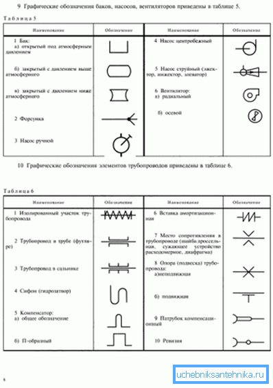
For some graphic designations, the document refers to the adjacent GOST:
- Pipelines should be designated in accordance with GOST 21.206 - 93.
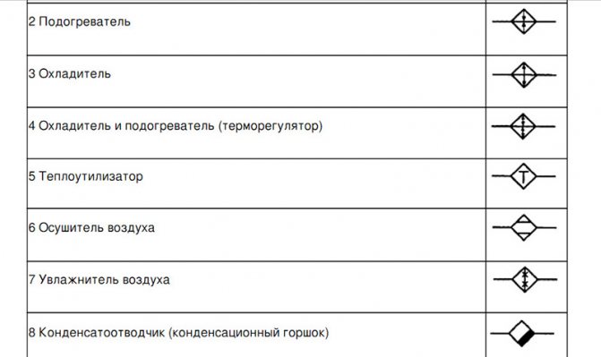
- Designations of check valves, throttles, gate valves, radiators, etc. can be found in GOST 21.205-93.
Fragment of the designation table from GOST 21.205 - 93.
In addition, among the general provisions, there are a number of additional requirements for drawings.
- Elevation marks are indicated on extension lines or feature outlines.
- The axonometric heating scheme can be performed on a scale of 1:50, 1: 100 and 1: 200.
List of designated equipment and parameters
On a self-made diagram, the following should be indicated:
- Pipelines with specified diameters.
- Thermal insulation of pipeline sections. She is depicted graphically.
- Levels of the axes of all pipelines relative to the zero mark.
- Dispensing slopes (of course, where they are needed - in gravity systems and top-filling houses).
In the gravity system, the slopes of the filling are indicated.
- If there are gaps in the horizontal sections of the filling - the size of the sections.
- Supports, expansion joints and suspensions.
An important point: in this case, the image is supplied with a shelf-extension, above which the type of element is indicated. The corresponding document should be indicated under the shelf.
- Shut-off valves. And in this case, an extension shelf is used, above which the type and diameter (DN) of the reinforcement is indicated. Below is the catalog item designation.
- Risers and beds (horizontal sections) with designations.
- Radiators, convectors and other heating devices.
Their type and basic parameters are mandatory:
- The number of sections of a sectional radiator.
- The number of sections (pipes) of the register and its length.
- Number and length of finned tubes.
- For other heating devices - their type.
- Designations of installations (boilers, furnaces with heat exchangers, heat pumps, elevator units, circulation pumps for heating, etc.).
- Embedded devices (oil cups for temperature control and taps for installing control valves to measure pressure).
- The instruments themselves for measuring system parameters and heat metering.
It is curious: GOST allows for multi-storey buildings to draw up a detailed scheme only for the underground part of the building. In this case, the riser wiring diagram and, if necessary, the attic wiring diagram are performed separately. The instruction is associated with the excessive complexity of the axonometric projection of all communications in, say, a 16-storey building.
Specifications
The standard sets out a number of requirements not only for the drawings themselves, but also for the specifications for them.
Items listed in the specifications must be entered in them in the following sequence:
- Heating equipment (boilers, radiators, etc.).
- Shut-off and control valves (valves, gate valves, throttles, check valves).
- Other elements of heating systems (mud collectors, discharges).
- Embedded structures (oil cups and taps for control valves).
It is curious: as a rule, in real conditions, the thermometers and manometers themselves are not installed in the embedded structures. The price of the devices is quite high; in the conditions of not reliably closing basements of apartment buildings, it is much more reasonable to dismantle them after the measurements have been taken.
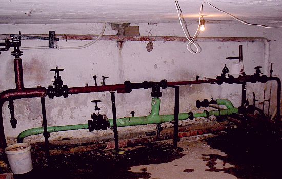
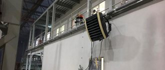
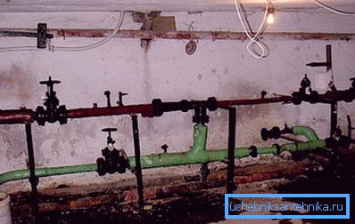
The photo shows a real elevator unit in the basement of an apartment building. Anything that can be stolen is removed.
- Pipelines (bottling, risers, connections).
- Thermal insulation.
The pipelines are entered into the specification for each diameter (as a rule, according to the increase in DU). Various elbows, flanges, weld crosses and bolts are not included in the specification.
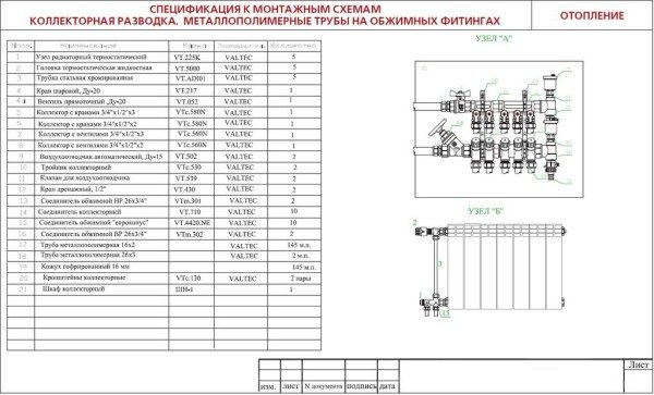
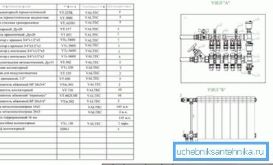
An example of a specification for a drawing of a heating manifold.
Features of a competent calculation
Only a specialist can calculate air heating, and the customer must check the points of the project, which include:
- Calculation of heat losses of each room. This is necessary to select the power of the air supply to heat the room.
- The type of heating equipment selected. The calculation takes into account the power of the unit, selected taking into account the real heat losses.
- Heating air volume. The calculation is based on the power of the selected heating source.
- The choice of the cross-section of air ducts and so on.
When ordering a project from a specialist, the user receives several options for arranging the circuit, from which he can choose what suits him best.
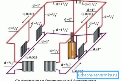
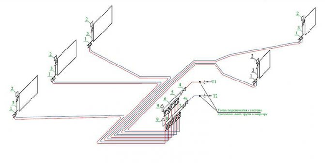
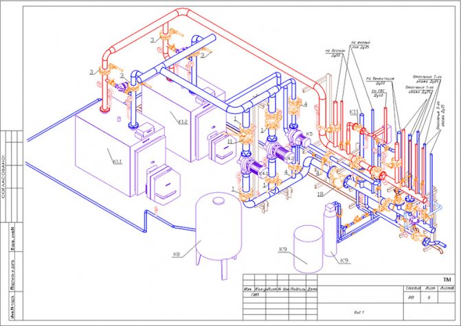
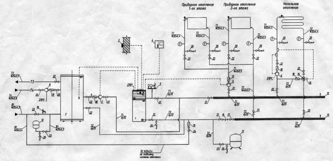
Axonometric diagram of the heating system
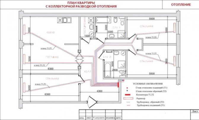
An axonometric diagram of a heating system is a graphical display of all nodes, pipes, units, valves and other similar elements. In this case, the diagram contains a description of the main characteristics for each device in the system.
An example of an axonometric heating scheme
Without the appropriate knowledge and skills, it is quite difficult to create an axonometry of heating, since you will need to take into account many interdependent factors, as well as make calculations. For multi-apartment buildings, all schemes are developed by specialists.
Airing principle
This is a type of microventilation system that assumes the removal of air along the shortest paths. For example, it can be a direct air outlet from a kitchen or bathroom.At the same time, unlike windows or other points of natural circulation, the modern principle of ventilation implies the possibility of regulating flows. These manipulations can be carried out both manually and by means of automation. The second option turns out to be more preferable, since it contributes to the formation of a microclimate close to natural. For example, in an apartment, air circulation according to the principle of automatic ventilation can be based on a change in the pressure indicator. The system takes wind speed into account, directing an optimal air flow into the room. Thanks to this, hypothermia is excluded and, in general, a comfortable temperature and humidity balance is established.
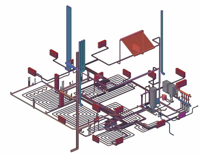
Axonometric diagram of heating and ventilation
Engineering networks require calculations and graphics. In addition to the plan of the building, its facade, the drawings show an axonometric diagram of communications. It clearly shows how this or that engineering network looks like. This is especially true for complex systems. So, ventilation can be performed from 2-3 elements, or it can have a complex design, where air ducts stretch through several rooms, distributing air. The heating project also provides for the implementation of axonometry in order to facilitate the work of installers during construction.
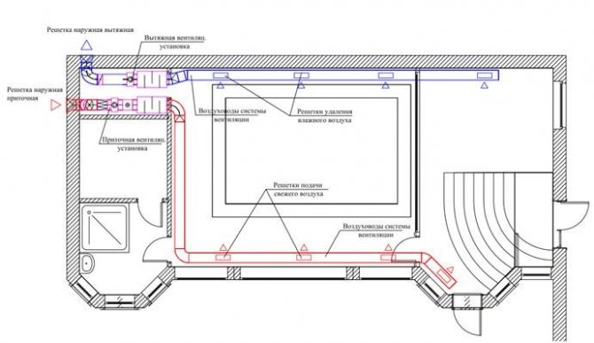
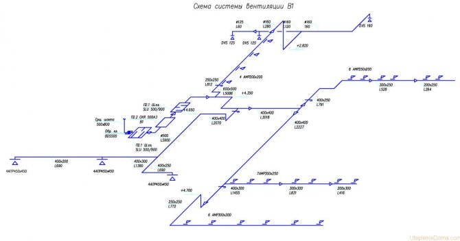
Rules for performing axonometry of supply and exhaust ventilation
Ventilation schemes are performed by engineers in frontal isometric view. This allows us to evaluate communications in three dimensions, which is due to the third axis. This feature distinguishes the axonometric ventilation scheme from plans and sections. You should start drawing a diagram by choosing the direction of the angle of view to the room or the entire structure where the exhaust or inflow will be carried out.
It is recommended to choose the direction from the side that is on the bottom of the drawing. If a sketch is being made, then you can draw as convenient. The main thing is then not to forget about the correct design of the final version. If this is not done on time, then part of the project will have to be redone. All air ducts are shown as solid thick lines. In this case, it is worth observing some features:
- a channel running parallel to the selected angle of view should be executed in the form of a horizontal line;
- vertical air ducts on an axonometric diagram are depicted by vertical lines;
- if the channel is located on the plan perpendicular to the selected viewing angle, then it should be applied to the sheet at an angle of 45 degrees;
- full compliance with the scale.
A number of requirements are put forward to the drawing that must be met by the designer.
Each duct is identified with an extension line. At the same time, the diameter (cross-sectional size) and air consumption are indicated. In addition, the height is indicated at different parts of the system. The axonometric ventilation diagram may contain local hoods - umbrellas. They are displayed with a legend. Fans, diffusers and other elements are also depicted with symbols. Equipment is marked with numbers.
Before heating in the garage, you need to insulate it well, preferably outside.
Heating axonometry: what to look for?
The implementation of a heating project for a residential building, administrative building or industrial facility involves drawing an axonometric diagram of the heating system. Before displaying the system on paper or in a computer program, it is necessary to carry out calculations. The scheme itself is drawn up on the basis of the following data:
- the value of the heat demand for each room in the building;
- type of heating devices, their number for each room;
- basic solutions for the entire engineering network, including the use of risers in the system, calculation of hydraulic branches and circuits, the procedure for connecting heating devices;
- characteristics of pipeline sections, namely: diameter, length of each pipe fragment, shut-off valves, thermal controllers, hydraulic regulators (in situations where pressure controllers are not pre-installed in the boiler unit).
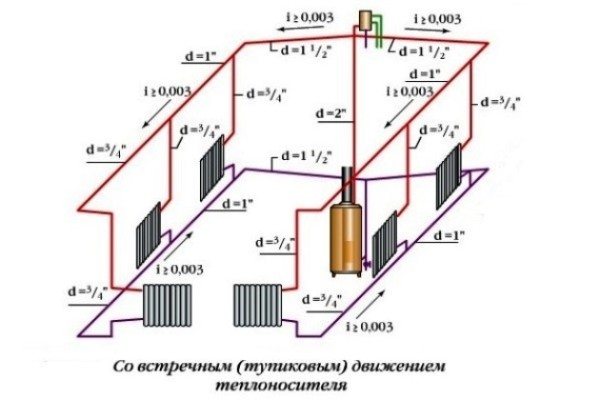
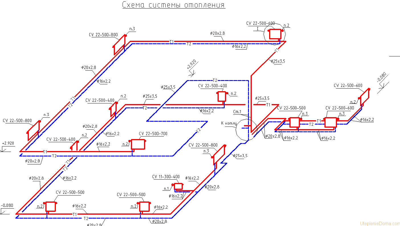
After performing the appropriate calculations, the obtained values are transferred to the drawing. The axonometric diagram of the heating system contains the characteristics of the equipment (boilers, pumps), the length and diameter of the pipelines, as well as the flow rate, and the thermal properties of heating devices (radiators, convectors, registers). When drawing an axonometry, it is necessary to determine the main ring of movement of the coolant. This is the path to the farthest element from the boiler and back.
One of the most convenient and quickest heating methods is heating the garage with an electric diode boiler.
Here you can read about heating a garage with used oil using a pyrolysis oven.
Diagram of a three-story house.
Axonometry is mandatory for heating and ventilation systems for buildings and structures of any purpose. This will allow installers to visualize what the network should look like. Competent reading of a correctly completed project will eliminate any difficulties when installing ventilation equipment and elements of the heating system.
In order to correctly design, and then carry out the installation of the utility network, it is necessary to correctly depict the structure itself and communications in it on a sheet or in electronic form. The graphic part of the project should include:
- general plan;
- situational plan;
- facade;
- ground, upper and middle floor plans;
- roof plan;
- axonometry of engineering networks;
- cuts and schematic diagrams.
It should be understood that when making drawings with a simple system that is located within one room, the cut can be omitted. In general, if the graphic part of the project, in particular the axonometry, is executed correctly, then there will be no problems with the installation.

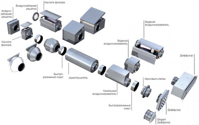
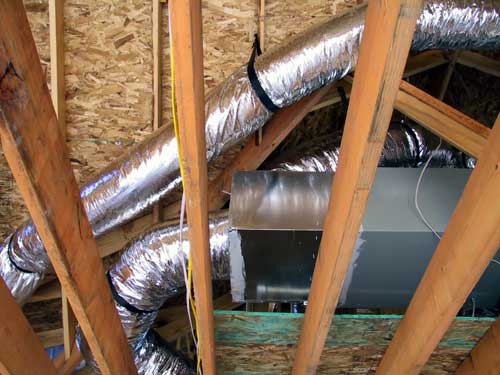
Technical organization of the air exchange system
There are different concepts and principles for arranging ventilation and ventilation systems. In the most optimized version, it will be a set of grilles with direct air exhaust ducts, ensuring the flow of street air. Standard home air circulation systems involve the organization of horizontal and vertical mines. This infrastructure is carried out using metal or plastic air ducts of different cross-sections. These can be rectangular and round, flexible and rigid structures, which are usually mounted according to the principles of concealed installation.
Drawings and diagrams for the heating system
Before installing a heating system in a house, you need to design it. When designing a heating system (diagrams and drawings), it is important to make them with the appropriate symbols.
This is necessary so that during further operation you can navigate in a functioning system. Focusing on it, you can easily find a breakdown and carry out its repair as soon as possible, since you will know the cause-and-effect relationship between the components of the heating system.
Natural ventilation
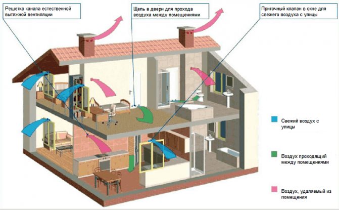
The device of this type of system is not very effective. Natural ventilation of a private house can only justify itself if the walls and roof are made of natural materials only.
The movement of air through the air ducts of the system is ensured by the temperature drop.
In the summer, the ventilation efficiency drops to zero, and the supply ventilation in a private house ceases to function.
Also, air movement is limited by the throughput. The design of plastic windows installed in most residential areas blocks the passage of air flows through them.
A ventilation device of this type is justified only if the house is located in an area with clean air. But, despite this, its use is due to a number of advantages:
- low cost in comparison with the other two types;
- maintaining optimal humidity in the premises;
- the ability to regulate the thermal regime in the house through proper design;
- inflow of clean air from outside;
- simple installation.
Natural ventilation can be done in two ways:
- laying of vertical channels in each room where ventilation of a private house is necessary;
- construction of a central shaft to which air ducts from each room are connected.
The second method requires a preliminary bookmark in the project. To implement the second method will require significant redevelopment and rebuilding of the house.
Symbols
There are special programs that help you correctly design the heating system of your home. Each heating scheme has its own symbols. They serve so that everyone can understand the drawing.
And accordingly, for general accessibility and ease of reading the heating system map, each component is indicated by a certain letter marking:
- "P" - supply systems, exhaust, installation of systems;
- "B" - installation of systems;
- "U" - air-type curtains;
- "A" - heating units.
These designations will be used for elements of the natural circulation heating system.
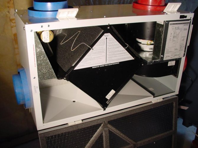
Which is better - natural or forced air movement?
The choice of the concept of an air exchange device is determined by the specific operating conditions of the room. This should take into account the merits of each system. In particular, the advantages of natural ventilation include:
- Inexpensive infrastructure available in build for private homeowners.
- The absence of mechanics eliminates the need for regular maintenance and laying of power supply lines.
- There are no maintenance costs. It is enough to periodically clean the channels, which requires minimal investment and effort.
- No noise due to a running fan.
The result is a simple system that is easy to use, but at the same time gives a modest effect in terms of ventilation.
Now you can consider the advantages of a forced air circulation system:
- It can provide sufficient ventilation regardless of external conditions.
- In addition to circulation as such, it allows you to perform the functions of cooling, heating and filtering air masses.
- The possibility of organizing a heat exchange system presupposes practically free heating of the incoming masses.
The disadvantages of forced air exchange are due to the difficulties in installation and maintenance of ventilation equipment, which, moreover, will require additional installation space.
Compulsory components
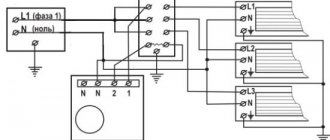
The following symbols will be used to calculate a forced heating system:
- "ST" - OS water riser;
- "GST" - the main water riser of the OS;
- "ГВ" - horizontal branch;
- "K" - compensator.
The heating system as a whole will be called "OS".
The diagrams present us with the heating system with the above markings. On the plan OS are shown by dots.
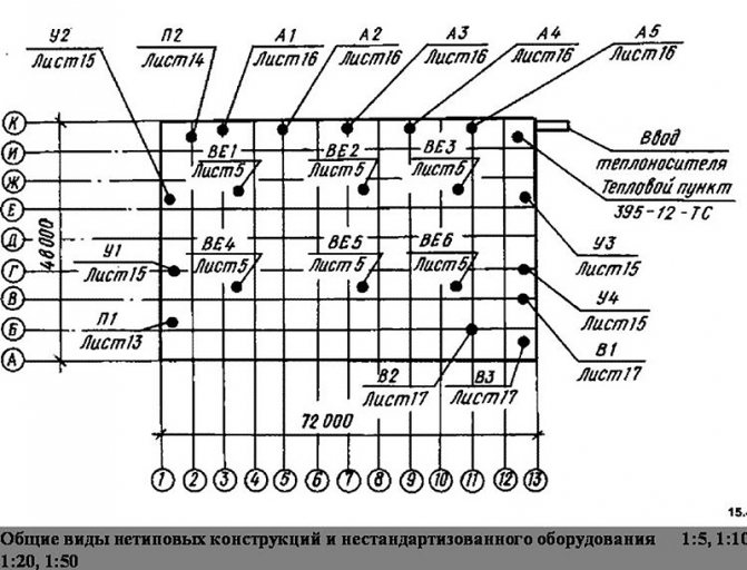
Their diameter is about 2 mm. Sectional heating systems, its drawings or diagrams are reproduced in the following scales:
- Ventilation and heating installations Layout, plan - 1 to 400, 1 to 800
- Sections and plans - 1 to 50, 1 to 100;
- Sections and plans - 1 to 100, 1 to 200
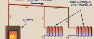
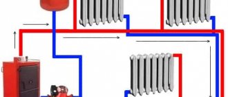
Heating circuit diagram
When designing the above data in detail, scales are used - 1 to 2, 1 to 5, 1 to 10. OS are not designed separately. More precisely, their separate image does not occur. Most often, one drawing, a diagram, combines an image of a heating system, a ventilation system and an indoor air conditioning system.
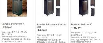
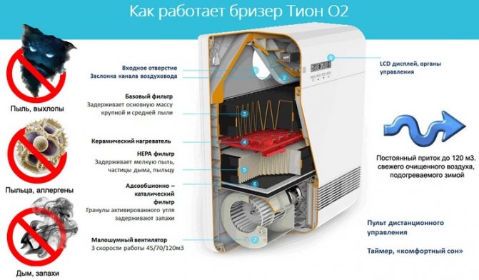
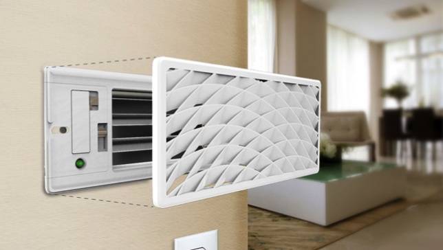
How can a fan heater be used
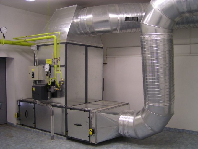
The purpose of fan heaters is similar to the purpose of heaters - the same heating of air masses. The difference between the devices lies in the design and operation features. Heaters can work as separate devices in active or passive ventilation lines.
A fan heater consists of heating elements (heating elements) or a heat exchanger paired with a fan. Moreover, everything is located in one building. The device creates forced circulation of air flow within an enclosed space and is designed to heat a small room.
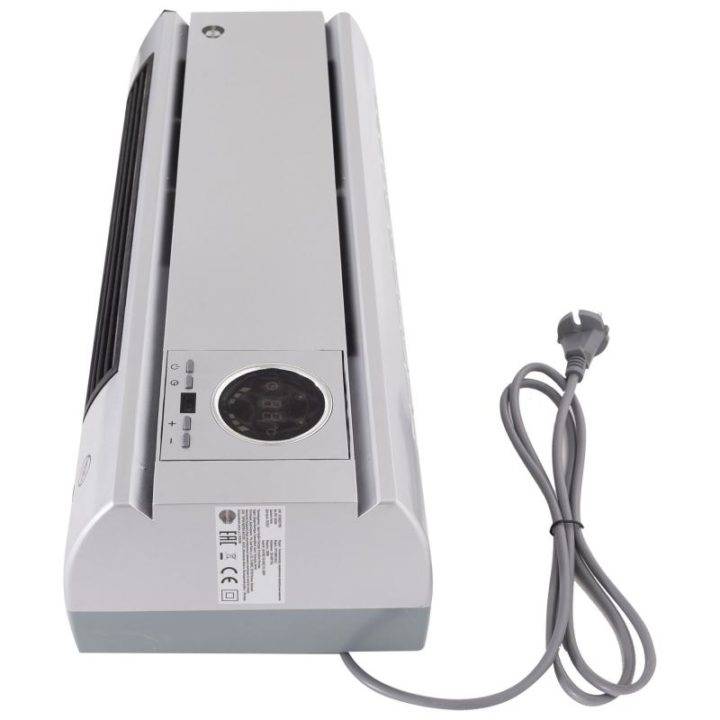
Wall mounted ceramic fan heater
Application options for fan heaters:
- as the main source of heat in the absence of central heating;
- as an additional source of heat to the main heating system;
- for quick heating of air in a small room;
- as a temporary or mobile heat source;
- in summer, the fan heater can be used as a regular fan if the heating elements are switched off.
Scheme options
Drawings and diagrams of the heating system, and as we have already found out the rest of the communications can be performed in different versions of axonometric projections. For people who closely study drawing and geometry, there will be no problems with the concept of axonometry. However, for those who are far from this area of knowledge, we present a transcript.
An axonometric diagram (or projection) for heating is one way of displaying geometric objects in a drawing using parallel projections. Divide into three types - isometric projection, dimetric and trimetric. By the number of axes - equal to three, equal to two and distorted three. This is how plans for heating systems with other communications are carried out.
Forced air circulation
As the number of mechanical devices in the duct system increases, air movement will increasingly conform to the principles of forced ventilation. The circulation in this case is stimulated by equipment (mainly fans), which can be dispersed in a wide variety of configurations. There are three models of forced air circulation:
- Exhaust - involves the removal of exhaust air from the room.
- Supply air - directs street air flows into the room.
- Supply and exhaust - at least, it works through two channels that perform two-way circulation.
In a domestic environment, during the operation of residential premises, supply and exhaust systems can be dispensed with. Unless kitchens, bathrooms and technical rooms require a complete recirculation infrastructure.